Amniotic fluid collector

a technology of amniotic fluid and collector, which is applied in the field of amniotic fluid collector, can solve the problems of structural organic distortion of organic film, deterioration of organic layer properties, and elevated surface temperature, so as to avoid pain, restlessness, and risk of complications of pregnant women.

Active Publication Date: 2013-01-31
SEOUL NAT UNIV R&DB FOUND
View PDF5 Cites 2 Cited by
  • Summary
  • Abstract
  • Description
  • Claims
  • Application Information

AI Technical Summary

Benefits of technology

[0008]To solve the problems as described above, the present invention provides an amniotic fluid collector capable of conveniently and efficiently colleting amniotic fluid from the uterus of a pregnant woman, without causing pains or psychological discomforts, and risks of complications of the pregnant woman.
[0012]The positioning portion may preferably include an expandable member which surrounds the receiving member and which is expandable upon injection of an injection material therein, to securely urge against an inner surface of the vagina and thereby secure the receiving member in position.
[0020]Because the amniotic fluid collector according to the present invention includes a receiving member having a receiving compartment, and a positioning portion for positioning the receiving member, it is possible to collect amniotic fluid from the uterus of the pregnant woman conveniently and efficiently, without causing pains, restlessness, or a risk of complications of a pregnant woman.

Problems solved by technology

The sputter coating has a problem in which collision of particles with energy generates defects and forms local trap sites, thereby causing a structural organic distortion of an organic film.
Also, the collision elevates a temperature of the surface and deteriorates properties of an organic layer.
However, when injecting a syringe, a pregnant woman may feel the pain and restlessness and there is a risk of developing complications and even medical accidents due to the examination.

Method used


Image

  • Amniotic fluid collector
  • Amniotic fluid collector
  • Amniotic fluid collector

Examples


Embodiment Construction

[0030]An amniotic fluid collector according to an embodiment of the present invention is configured to be inserted into vagina of a pregnant woman and positioned therein to collect amniotic fluid from the uterus of the pregnant woman.

[0031]An amniotic fluid collector according to an embodiment of the present invention is configured to be inserted into vagina of a pregnant woman and positioned therein to collect amniotic fluid from the uterus of the pregnant woman.

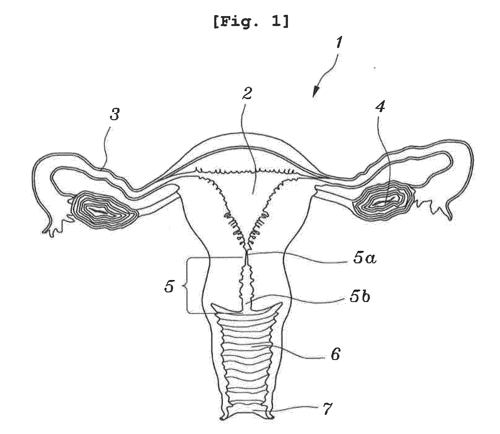
[0032]The reproductive organs 1 of a woman include an external reproductive organ including a vaginal entrance 7, and internal reproductive organs including vagina 6, uterus 2, fallopian tubes 3 and ovaries 4.

[0033]The ovaries 4 are where ovum is produced and female hormones are released. The ovulation occurs in the ovaries 4 in which a matured ovum is released.

[0034]In detail, as a result of ovulating alternately, eggs are released from both ovaries 4 once in two months, that is, an egg comes out once in a month.

[0035]Also...


PUM


Abstract

According to the present invention, an amniotic fluid collector is configured so as to be inserted and positioned inside the vagina of a birthing mother in order to collect amniotic fluid from the womb of the birthing mother. In particular, the amniotic fluid collector of the present invention comprises: a receiving member, in the side of which an opening is defined, which is inserted into the vagina of the birthing mother and which has a receptacle defined therein for receiving the amniotic fluid; and a positioning portion for positioning the receiving member inside the vagina. Thus, the effects of alleviating pain and psychological anxiety of a birthing mother and eliminating the danger of the occurrence of complications can be achieved, as well as those of easily and smoothly collecting amniotic fluid from the womb of the birthing mother.

Description

BACKGROUND OF THE INVENTION[0001]1. Field of the Invention[0002]The present invention relates to an amniotic fluid collector, and more particularly, to an amniotic fluid collector capable of conveniently and efficiently collecting amniotic fluid from the uterus of a pregnant woman, while eliminating pains or psychological anxiety of the pregnant woman, and also eliminating risk of complications of the pregnant woman.[0003]2. Description of the Related Art[0004]Generally, in the uterus of a pregnant woman, there are a fetus and amniotic fluid. Also, along the pregnancy, various medical examinations are performed with respect to a pregnant woman and fetus.[0005]Particularly, amniotic fluid is generally collected from the uterus of a pregnant woman to check whether there are a sign of premature labor, an infection in amniotic fluid, an inflammation and infection in a fetus, a damage of a fetus, a fetal maturity, fetal diseases, and fetal deformities and also to examine ingredients of a...

Claims


Application Information

Patent Timeline
Patent Type & Authority Applications(United States)
IPC IPC(8): A61B5/00
CPCA61B10/0048A61M1/0009A61B17/4208A61B10/0045A61M1/67
Inventor YOON, BO HYUNPARK, CHAN WOOKLEE, SEUNG MIPARK, JOONG SHIN
Owner SEOUL NAT UNIV R&DB FOUND
Why Eureka
Try Eureka