Leg Prosthesis

a lower limb and prosthesis technology, applied in the field of lower limb prosthesis, can solve the problems of not being able to accommodate the shin portion between the distal limb and the knee chassis, the adaptation of each prosthesis according to the height of the amputee is an expensive and material-intensive process, and the arrangement has not been used for above-knee amputees

Inactive Publication Date: 2013-01-31
BLATCHFORD PRODS
View PDF3 Cites 10 Cited by
  • Summary
  • Abstract
  • Description
  • Claims
  • Application Information

AI Technical Summary

Problems solved by technology

However, such an arrangement suffers from the disadvantage that the interface between the distal limb portion and the knee chassis does not accommodate a shin portion which can store and return energy during a stride.
Furthermore, such known arrangements suffer from the disadvantage that the adaptation of each prosthesis according to the amputee's height is an expensive and material-intensive process.
However, such arrangements have not been used for above-knee amputees as the resilience of this member has been found to interfere with the control of the knee portion necessary for control of the limb.

Method used


Image

  • Leg Prosthesis
  • Leg Prosthesis
  • Leg Prosthesis

Examples


Embodiment Construction

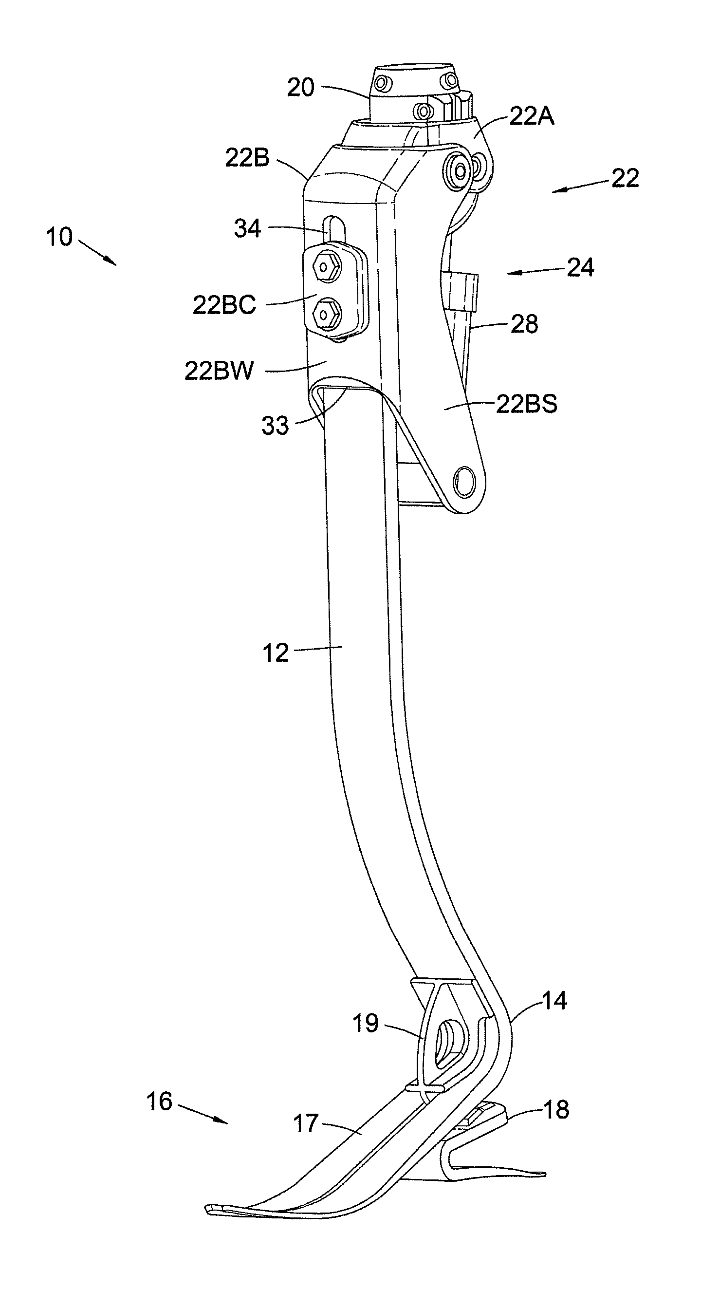
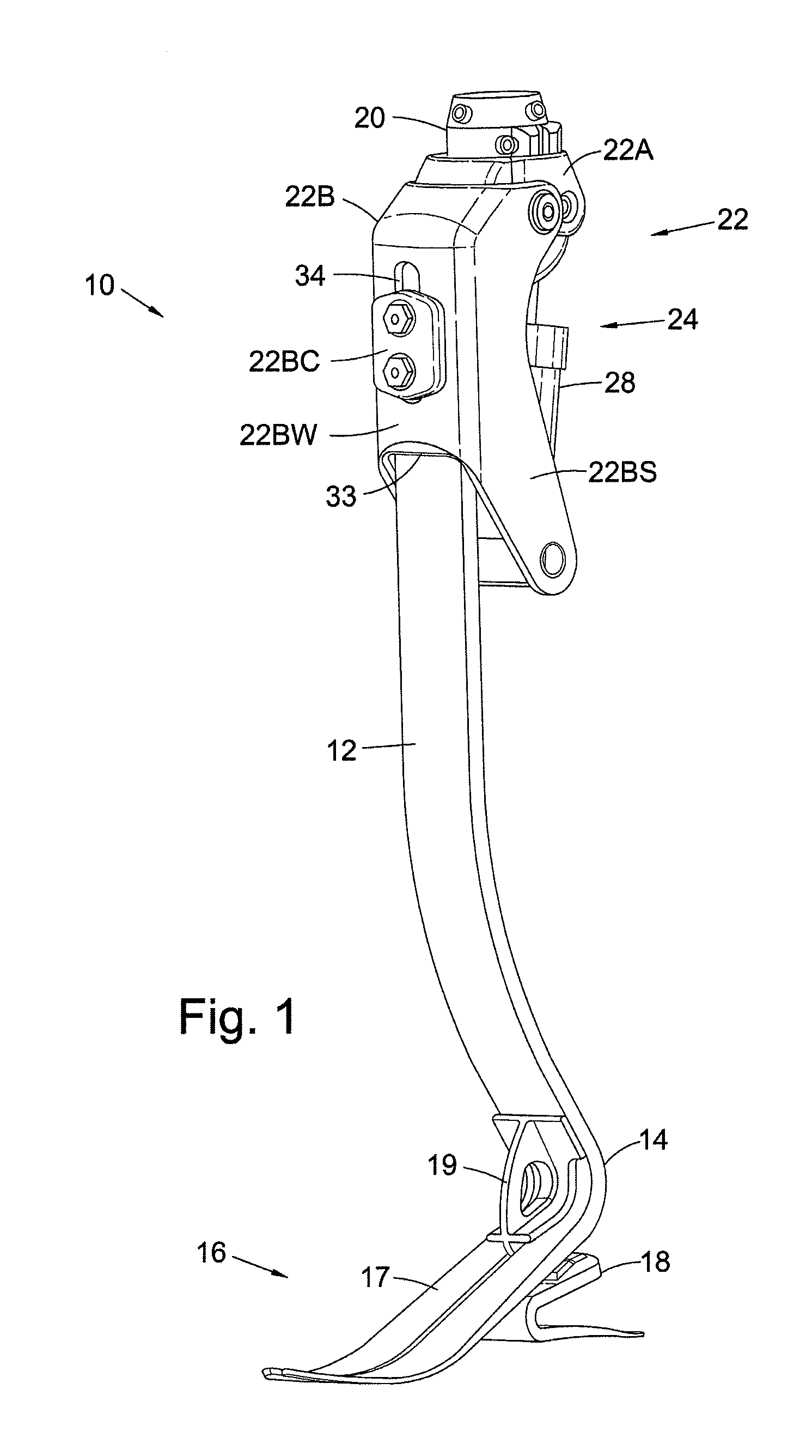
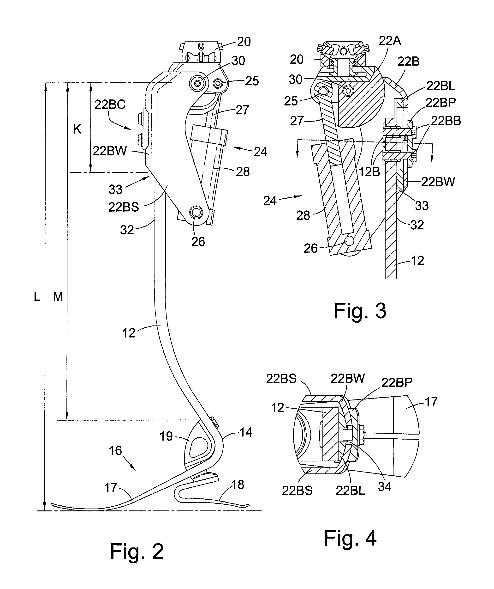
[0023]Referring to FIGS. 1 to 4, a first prosthesis 10 according to an embodiment of the invention comprises a shin portion 12, an ankle portion 14 and a foot portion 16. In this embodiment, the shin portion 12, ankle portion 14, and a forefoot part 17 of the foot portion 16 are formed as a single resilient integral member of laminated composite carbon fibre. The use of this material for this application is known and provides energy storage and transmission characteristics which simulate a natural limb. Other fibre-reinforced materials may be used such as materials made with Kevlar®. Although the shin portion 12, ankle portion 14 and the forefoot part 17 are formed as a single, resilient integral member they are referred to herein as separate portions of the same member.

[0024]The single, integral member forming the shin portion 12, ankle portion 14 and the forefoot part 17 is a blade. The medial-lateral extent of a cross-section of the blade is significantly greater than the anterio...


PUM


Abstract

A lower limb prosthesis for a transfemoral amputee, having a shin portion, ankle portion and a forefoot part of the foot portion formed as an integral fibre-reinforced plastics leaf spring component. This integral component is adjustably mounted to a knee joint which has a knee chassis, a cradle pivotally connected to and depending from the knee chassis, and a flexion control unit in the form of a piston and cylinder assembly interconnecting the knee chassis and the cradle. The shin portion has an elongate resilient section of constant cross-section oriented substantially vertically. The connection of this resilient section to the knee joint cradle and the arrangement of the cradle is such that the vertical distance between the knee axis of rotation and the location of the connection is less than 25% of the vertical distance between the knee axis and the lowest weight-bearing surface of the foot portion.

Description

FIELD OF THE INVENTION[0001]This invention relates to a lower limb prosthesis and, in particular, to a lower limb prosthesis for a transfemoral amputee.BACKGROUND OF THE INVENTION[0002]A known lower limb prosthesis includes a distal limb portion and a knee portion, the knee portion comprising a knee chassis having knee controls; the distal limb portion is then connected to a frame which receives the knee chassis of the knee portion. The knee controls located within the knee chassis control the movement of the distal limb portion. An example of such an arrangement is disclosed in GB 2 432 317.[0003]However, such an arrangement suffers from the disadvantage that the interface between the distal limb portion and the knee chassis does not accommodate a shin portion which can store and return energy during a stride. Furthermore, such known arrangements suffer from the disadvantage that the adaptation of each prosthesis according to the amputee's height is an expensive and material-intens...

Claims


Application Information

Patent Timeline
Patent Type & Authority Applications(United States)
IPC IPC(8): A61F2/60A61F2/64A61F2/62
CPCA61F2/60A61F2002/764A61F2002/6678A61F2/642A61F2002/502A61F2002/5055A61F2002/5079A61F2002/608A61F2002/6664A61F2002/6671A61F2002/704A61F2002/74A61F2002/7625A61F2002/7635A61F2002/607A61F2/74A61F2/64A61F2/68
Inventor ZAHEDI, MIR SAEEDHARRIS, GRAHAMMCCARTHY, JOSEPH
Owner BLATCHFORD PRODS
Why Eureka
Try Eureka