System and method for use in monitoring machines

a monitoring machine and system technology, applied in the field of monitoring systems, can solve the problems of machine operators being unwary of certain behaviors, machine operators may experience deviations from normal operation, and anomalies remain unnoticed and unexplained

Inactive Publication Date: 2013-01-31
GENERAL ELECTRIC CO
View PDF0 Cites 52 Cited by
  • Summary
  • Abstract
  • Description
  • Claims
  • Application Information

AI Technical Summary

Problems solved by technology

During operation of some of these known machines, the machines may experience deviations from normal operation.
Moreover, such anomalies may not be recognized during a review of the data collected during the anomalies, if the data is reviewed at all, and the anomalies will remain unnoticed and unexplained.
These anomalies may be indicative of impending, more severe deviations from normal operation, including sudden and / or catastrophic failure of the machine.
Therefore, operators of the machine may remain unwary of certain behaviors and / or conditions of the machine that may indicate a potentially pending, or imminent, failure.
Moreover, such historical data reviews are time-consuming, resource-intensive, and, therefore, expensive.
Typically, the transformed waveform data used is limited to frequency data and amplitude data.
These known computer-implemented models may not be generated with sufficient spectral analysis data and / or empirical data to fully and accurately define the machine, the associated processes, and / or associated faults.
Moreover, limiting the real-time analysis of spectral data to frequencies and amplitudes of the collected waveforms extends the analysis time and / or response time of the model, thereby delaying responses by the operators.
Furthermore, the use of limited spectral data increases the reliance on the use of empirical data to generate the models, thereby increasing the complexity of the models, and therefore increasing the maintenance requirements of the models.

Method used


Image

  • System and method for use in monitoring machines
  • System and method for use in monitoring machines
  • System and method for use in monitoring machines

Examples


Embodiment Construction

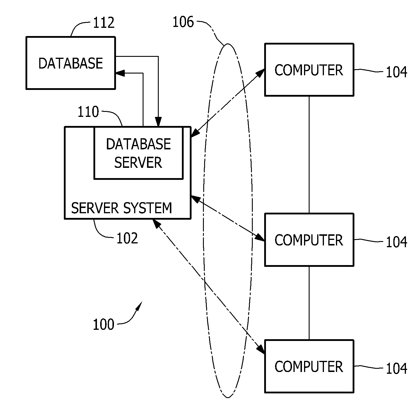
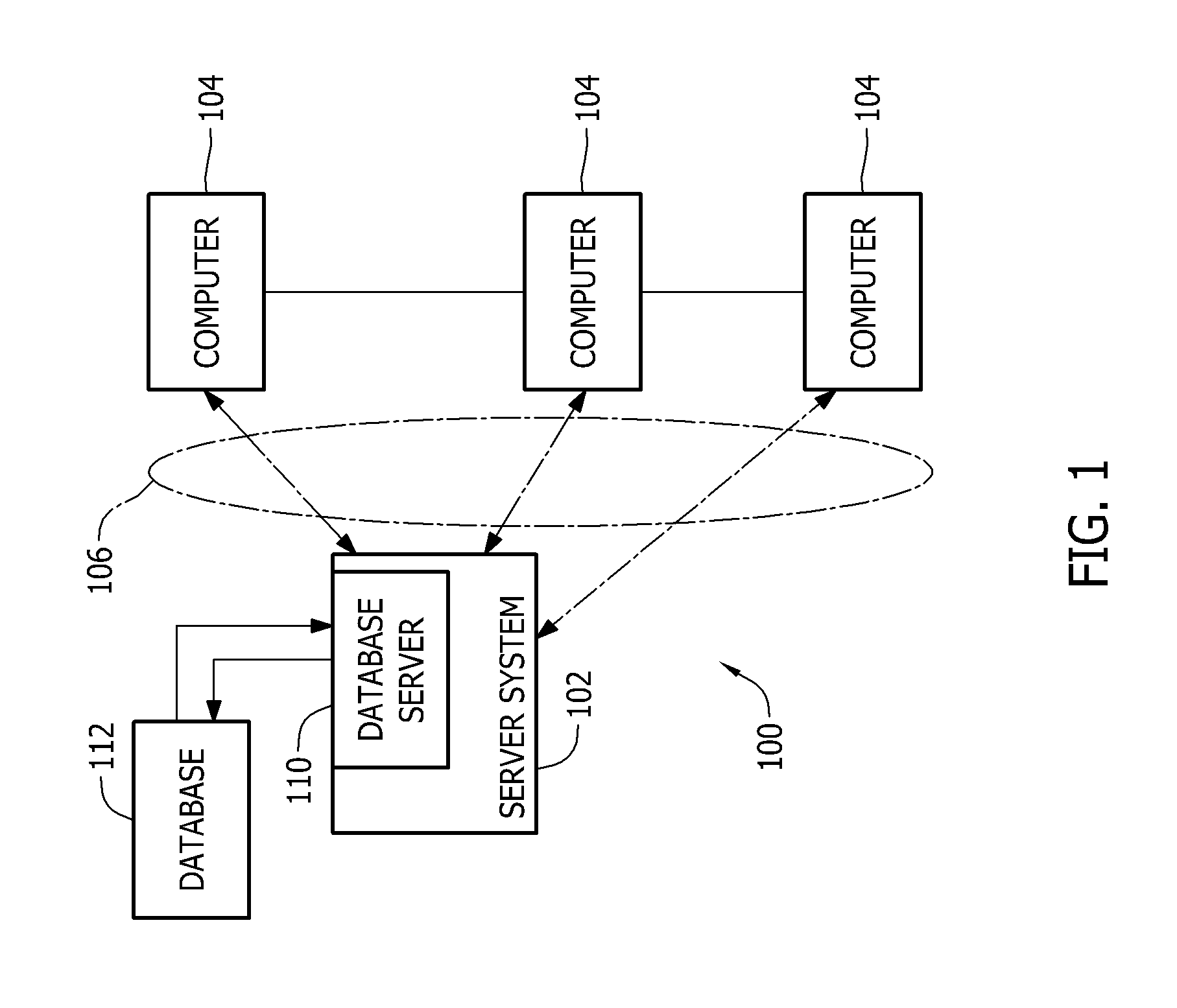
[0016]FIG. 1 is a simplified block diagram of a typical server architecture of a monitoring system 100. In the exemplary embodiment, monitoring system 100 facilitates collecting, storing, and displaying data associated with operation of machines (not shown) in an industrial facility (not shown). Also, in the exemplary embodiment, monitoring system 100 includes a server system 102 communicatively coupled to a plurality of client systems 104, which may include one or more input devices (not shown in FIG. 1).

[0017]Further, in the exemplary embodiment, client systems 104 are computers that include a web browser, which enable client systems 104 to access server system 102 using a communications network 106 integrated within monitoring system 100. At least a portion of communications network 106 forms a backbone of monitoring system 100. More specifically, client systems 104 are communicatively coupled to server system 102 through at least one of many possible interfaces including, withou...


PUM


Abstract

A system for monitoring a machine includes a memory device operatively coupled with a processor. The memory device stores a plurality of operational measurements of the machine and is programmed with computer instructions that instruct the processor to record a first plurality of operational measurements of the machine, perform a full spectrum analysis thereof, and generate a first full spectrum data set therefrom. The instructions also instruct the processor to transmit the first full spectrum data set to a model stored within the memory device. The instructions further instruct the processor to determine variations between the first full spectrum data set and a second full spectrum data set. The second full spectrum data set is different from the first full spectrum data set.

Description

BACKGROUND OF THE INVENTION[0001]The subject matter disclosed herein relates generally to monitoring systems and, more specifically, to systems and methods for use in monitoring the physical condition of a machine.[0002]Many known industrial facilities include a plurality of known rotating and reciprocating machines. At least some such known machines include turbomachines, pumps, motors, compressors, diesel engines, gear boxes, and fans. At least some of such known industrial facilities are power generation facilities that include at least some of the known turbomachines, such as gas turbine engines and steam turbogenerators.[0003]Many known machines include components that receive monitoring equipment for real-time data acquisition and off-line diagnostics. Such known components include, for example, rotatable shafts and associated bearings. Also, such known monitoring equipment includes, for example, proximity probes, vibration sensors and temperature sensors. During routine and n...

Claims


Application Information

Patent Timeline
Patent Type & Authority Applications(United States)
IPC IPC(8): G06F15/00
CPCG05B23/024
Inventor DAVID, DANNI
Owner GENERAL ELECTRIC CO
Why Eureka
Try Eureka