Shoe soles for shock absorption and energy return

a technology of energy return and shock absorption, which is applied in the field of shoes, can solve the problems of the heel hitting the ground, and achieve the effects of reducing manufacturing costs, improving the speed of sole rebound, and reducing the deformation of a resiliently compressible layer

Active Publication Date: 2013-02-07
NEWTON RUNNING CO INC
View PDF29 Cites 70 Cited by
  • Summary
  • Abstract
  • Description
  • Claims
  • Application Information

AI Technical Summary

Benefits of technology

[0005]Various exemplifying embodiments of shoe soles incorporating layered combinations of materials including at least one resiliently compressible portion are disclosed herein. Some embodiments of shoe soles incorporating features disclosed herein can provide improved speed of sole rebound when the sole undergoes a compression and decompression cycle in use, greater resistance to long-term deformation of a resiliently compressible layer, reduced manufacturing costs compared to some prior art shoe soles, or a combination of some or all of these benefits.
[0008]In some embodiments, such as those described above, the foundation and the resiliently compressible element can be sized and shaped to closely correspond to each other. In some embodiments, this close correspondence between the size and shape of the foundation and the resiliently compressible element can control expansion of the resiliently compressible element in a direction that is transverse to a direction of compression of the resiliently compressible element such that transverse expansion is inhibited, restricted, substantially prevented, or prevented.
[0010]In embodiments wherein the shoe sole comprises a plurality of plate elements, such as those mentioned above, the plate elements can optionally be elastically interconnected. The elastic interconnections can urge one plate element toward a position aligned with an adjacent element or elements when moved out of alignment with the adjacent element or elements, whether by movement out of alignment from a nominal plane or surface, by increased separation in a direction along a nominal plane or surface, or a combination thereof. Such arrangements can increase the speed of rebound from compression of the shoe sole and improve the return of energy to the shoe wearer.
[0011]In embodiments wherein the shoe sole comprises a plurality of lugs, such as those mentioned above, the lugs can optionally be elastically interconnected. The elastic interconnections can urge one lug toward a position aligned with an adjacent lug or lugs when moved out of alignment with the adjacent lug or lugs. Such arrangements can increase the speed of rebound from compression of the shoe sole and improve the return of energy to the shoe wearer. The ground reaction force of the wearer's foot acting on the shoe as it engages the ground (impact) can cause one or more of the lugs to be forced upward into sole. This force is resisted and stored by elastic portions, if any, which connect a lug to an adjacent lug or lugs and by the resiliently compressible material. Some embodiments including such arrangements can demonstrate improved shock attenuation and greater efficiency than prior art soles.
[0013]In some embodiments, a shoe sole can have at least one resiliently compressible element removably received in a foundation such that, between uses of the shoe, one resiliently compressible element can be removed and replaced with another resiliently compressible element that is substantially the same as the first or different from the first. In some such embodiments and in some other embodiments, a plate or plate elements can be attached to an insole or sockliner such that the plate or plate elements can be removed with the insole, and then inserted again to the shoe with the plate or plate elements appropriately positioned relative to the at least one resiliently compressible element. This feature can, in some embodiments, facilitate an exchange of at least one resiliently compressible element with another.

Problems solved by technology

The heel of the foot may strike the ground in a walking gait, when the runner has adapted to wearing an elevated heel or when the running form is inefficient.

Method used


Image

  • Shoe soles for shock absorption and energy return
  • Shoe soles for shock absorption and energy return
  • Shoe soles for shock absorption and energy return

Examples


Embodiment Construction

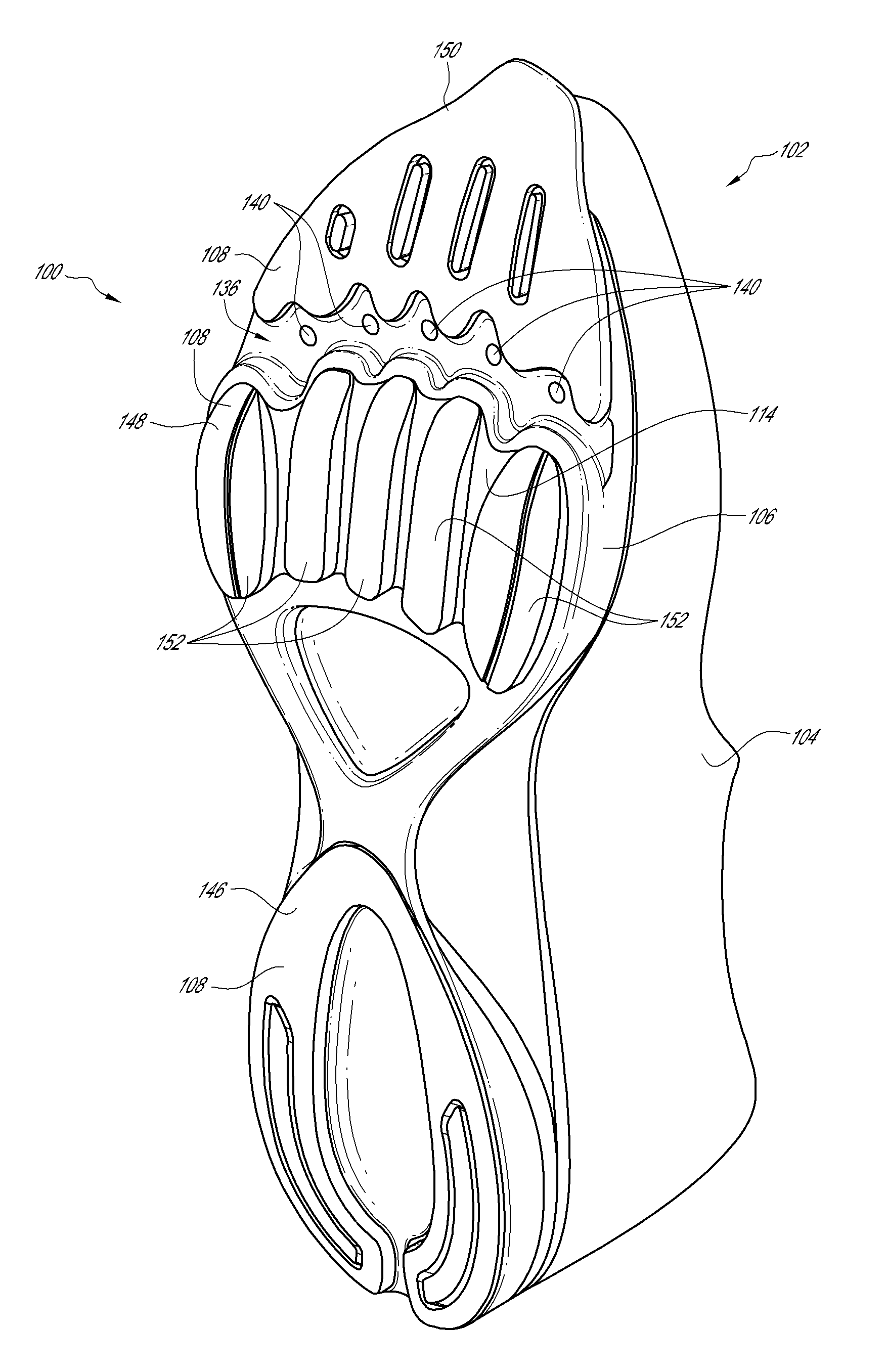
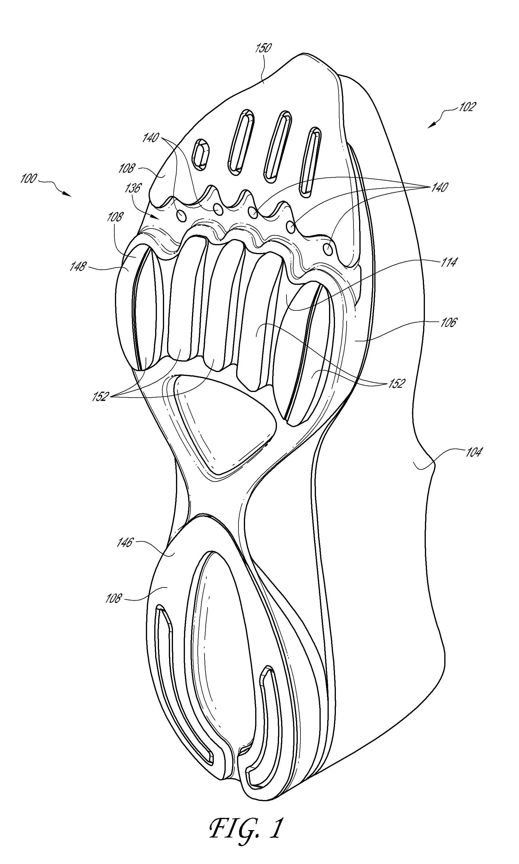
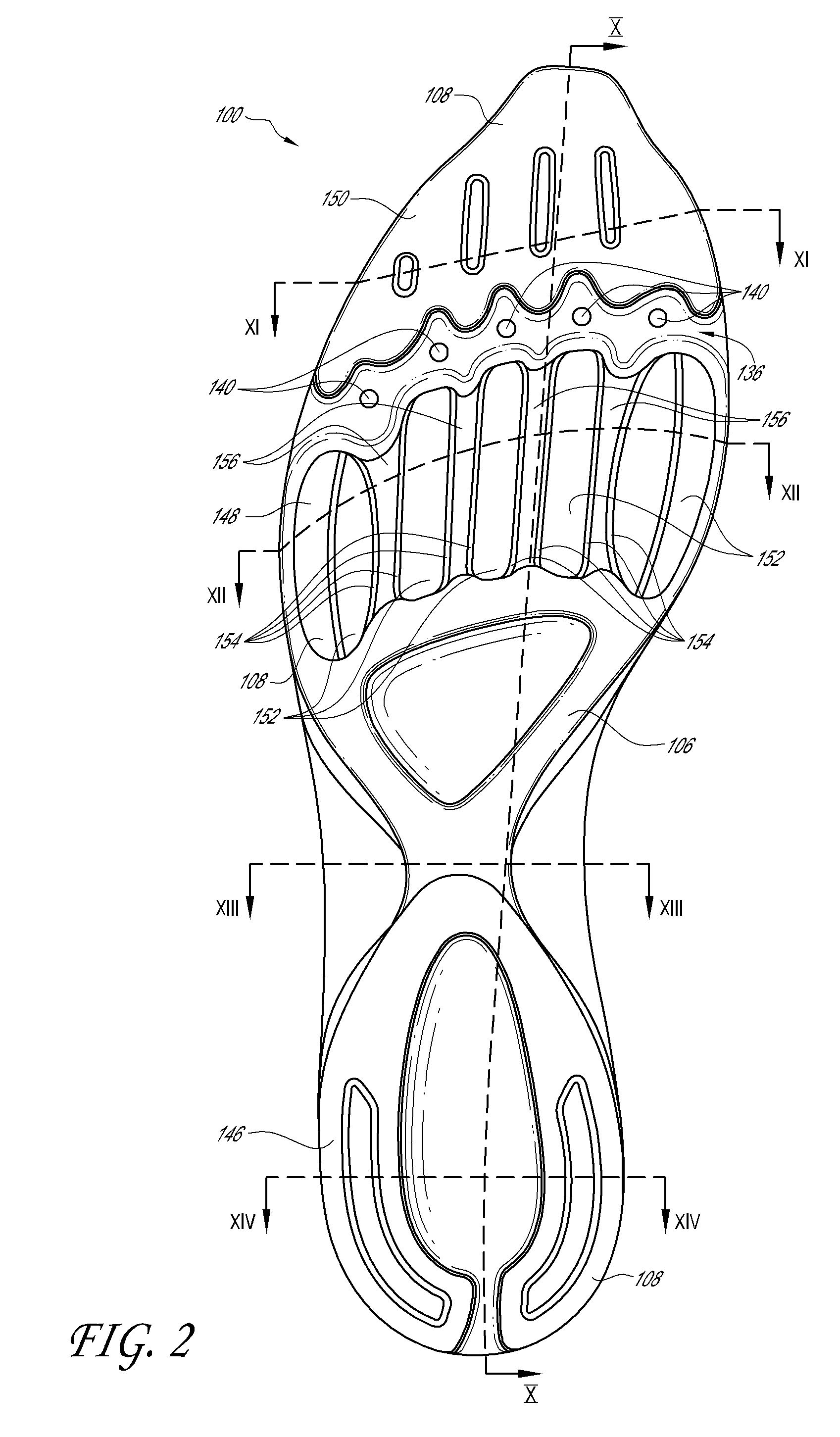
[0040]FIGS. 1-3 illustrate an embodiment of a shoe 102 exemplifying various inventive aspects and features. As illustrated in FIG. 1, the shoe 102 can comprise a sole 100 and an upper 104. The shoe sole 100 can comprise a foundation 106, an outsole 108, at least one resiliently compressible element 110, and at least one plate 112. In some embodiments, the sole 100 can comprise one or more elastic membranes 114, which can be integrally formed with or separately formed then attached to the foundation 106, the outsole 108, the plate 112, or a combination of them, such as further described below for example. The upper 104, shown schematically in FIG. 1, is omitted from FIGS. 2-3.

[0041]In the embodiment illustrated in FIGS. 1-3, the foundation 106 can form a layer of the sole that underlies the entire foot or substantially the entire foot between toe and heel and between lateral and medial sides. In some embodiments, the foundation 106 can comprise a plurality of foundation elements, whi...


PUM


Abstract

A shoe sole can comprise one or more resiliently compressible elements received in a foundation and located by the foundation to underlie a portion of a foot, such as metatarsal heads, when the shoe is worn. The resiliently compressible element or elements can be shaped to reduce coupling of compression of adjacent regions of the resiliently compressible element. One or more plate elements can be positioned between the resiliently compressible elements and the foot, e.g. under the metatarsal heads. The plate elements can be separated from each other by spaces, such as slots, to reduce coupling of movement of adjacent plate elements. The plate elements can be elastically interconnected at the spaces between them. A plurality of lugs configured to contact the ground can be located on a lower surface of the foundation such that they are generally aligned with the plate elements. The plurality of lugs can be elastically interconnected.

Description

FIELD OF THE DISCLOSURE[0001]The present disclosure generally relates to articles of footwear, and more particularly, to shoe soles that may be incorporated into athletic footwear, as an insert into existing footwear, or both.BACKGROUND[0002]In typical walking and running gaits, one foot contacts a support surface (such as the ground) in a stance mode while the other foot moves through the air in a swing mode. During the stance mode, the foot in contact with the support surface travels through three successive basic phases: strike, mid stance and toe off. With efficient running and natural running form, the foot may strike the ground forward of the heel. The heel of the foot may strike the ground in a walking gait, when the runner has adapted to wearing an elevated heel or when the running form is inefficient.[0003]Running shoe designers have sought to strike a compromise between providing enough cushioning to protect the runner's foot, but not so much that the runner's foot will co...

Claims


Application Information

Patent Timeline
Patent Type & Authority Applications(United States)
IPC IPC(8): A43B13/18
CPCA43B7/1425A43B7/1435A43B7/144A43B7/1445A43B13/189A43B7/149A43B13/122A43B13/145A43B13/187A43B7/145A43B13/183A43B13/185A43B13/188A43B7/1464
Inventor ABSHIRE, DANNY
Owner NEWTON RUNNING CO INC
Why Eureka
Try Eureka