Method and system for unveiling hidden dielectric object

a dielectric object and hidden technology, applied in the field of electric engineering, can solve the problems of not being able to use this method in the field of remote determination, unable to achieve the effect of determining the dielectric, and requiring the parallel arrangement of the layers of the dielectric obj

Active Publication Date: 2013-02-07
APSTEC SYST
View PDF1 Cites 18 Cited by
  • Summary
  • Abstract
  • Description
  • Claims
  • Application Information

AI Technical Summary

Benefits of technology

[0013]The dielectric permittivity of a dielectric object is determined when the object is placed against the background of a reflector. The method includes recording a 3D microwave and a 3D optical range images of an interrogated scene at the same time moment, digitizing all images and overlapping them in one common coordinate system; determi...

Problems solved by technology

The disadvantage of this method is that it requires a contact between the emitter and the object, the dielectric permittivity of which is to be determined.
These requirements do not allow using this method for remote determination of the dielectric permittivity of objects.
The disadvantage of this method, which is taken as a prototype for the present invention,...

Method used


Image

  • Method and system for unveiling hidden dielectric object
  • Method and system for unveiling hidden dielectric object
  • Method and system for unveiling hidden dielectric object

Examples


Embodiment Construction

[0023]In the following description, for purposes of explanation, specific examples are set forth to provide a thorough understanding of the present invention. However, it will be apparent to one skilled in the art that these specific details are not required in order to practice the present invention. The same techniques can easily be applied to other types similar systems.

[0024]Implementation of the distinguishing features of the invention results in new important features of the claimed subject matter. In particular the invention makes it possible to remotely determine the dielectric permittivity of a moving, irregularly-shaped dielectric object.

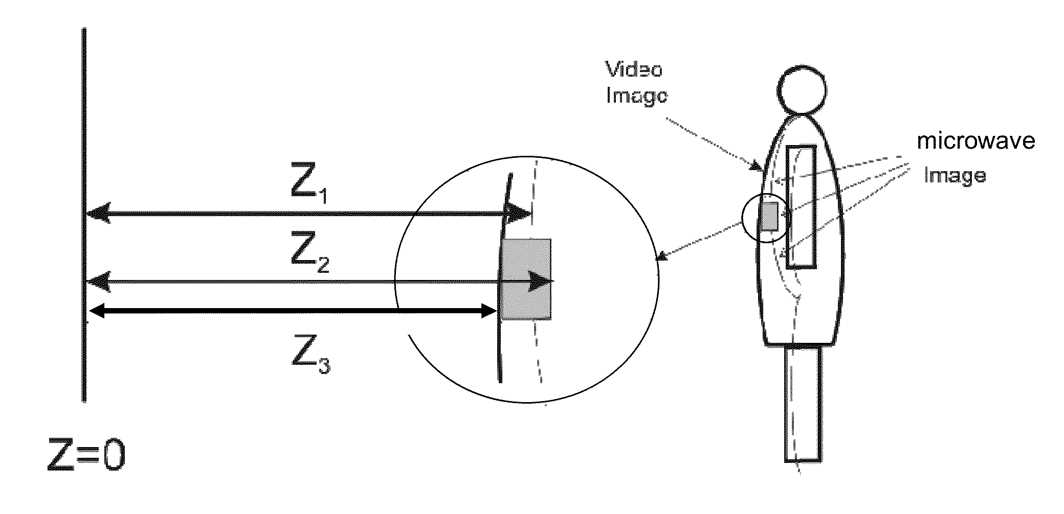
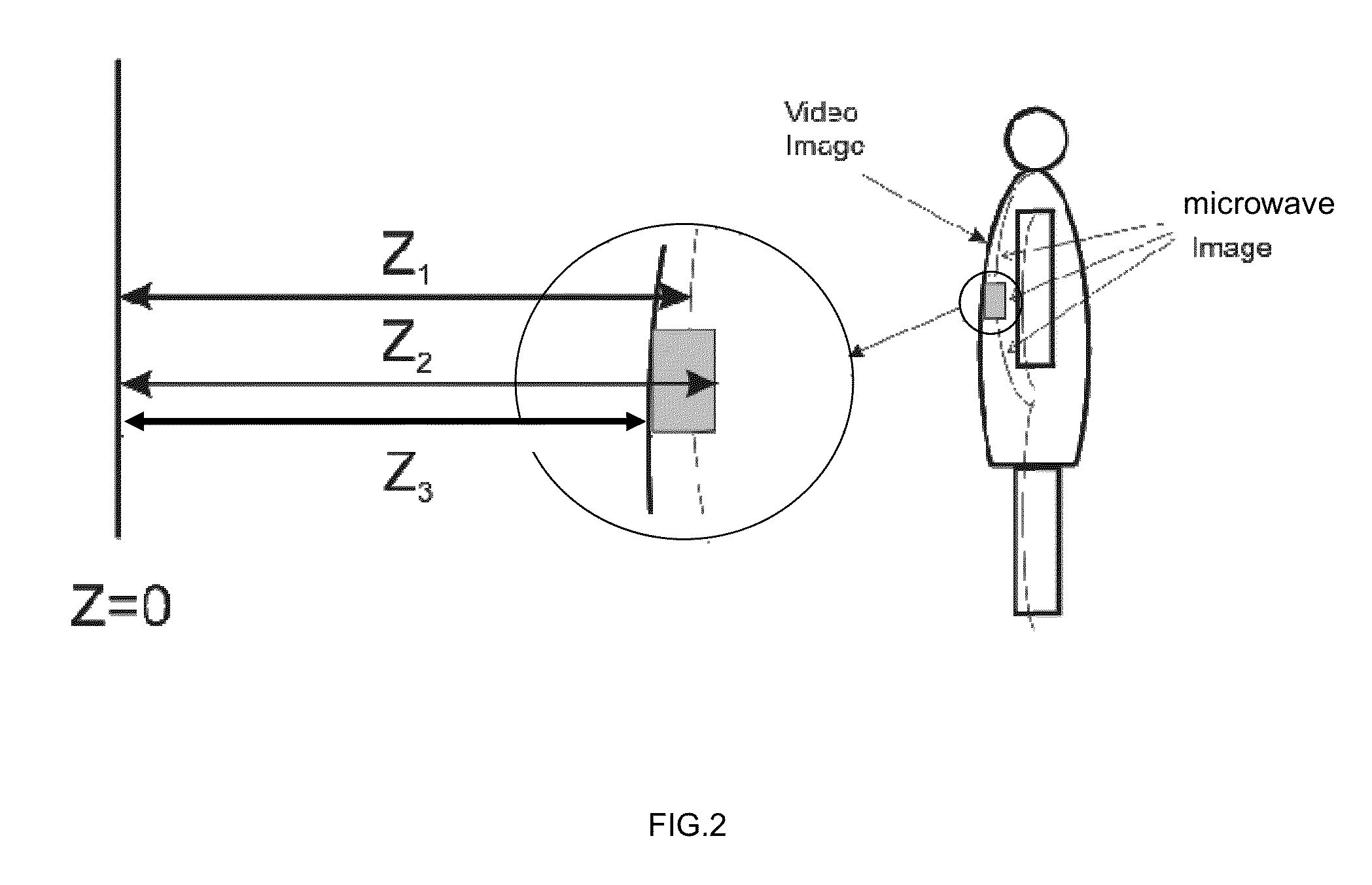
[0025]In order to demonstrate the method for determining the dielectric permittivity of a dielectric object against the background of a reflector, a test dummy was used to mimic the human body serving as the reflector. The dummy had a dielectric object (beeswax) attached to the body. The goal of the experiment was to determine the dielectr...


PUM


Abstract

The invention relates to the remote measurement of the dielectric permittivity of dielectrics. A 3D microwave and a 3D optical range images of an interrogated scene are recorded at the same time moment. The images are digitized and overlapped. A space between the microwave and optical image is measured, and a dielectric permittivity of the space between these images is determined. If the dielectric permittivity is about 3, then hidden explosive materials or components of thereof are suspected. The invention makes it possible to remotely determine the dielectric permittivity of a moving, irregularly-shaped dielectric objects.

Description

CROSS-REFERENCE TO RELATED APPLICATIONS[0001]This application is a Continuation-in-part of U.S. patent application Ser. No. 13 / 120,494 filed Aug. 4, 2011 and U.S. patent application Ser. No. 13 / 403,256 filed Feb. 23, 2012.FIELD OF INVENTION[0002]The invention relates to the field of electrical engineering and, more specifically, to the remote measurement of the dielectric permittivity of dielectrics. In particular, it provides a method and system for detection of dielectric explosive substances concealed under clothes on the human body.BACKGROUND OF THE INVENTION[0003]One of known methods for determining the dielectric permittivity of a material consists of irradiating a sample with an electromagnetic wave using a double-arm emitter, changing difference between the signal's phases in the arms of the emitter and measuring amplitude of the wave transmitted at an angle and determining the dielectric permittivity. By changing the difference between the signal's phases in the arms of the...

Claims


Application Information

Patent Timeline
IPC IPC(8): H04N13/02H04N5/30
CPCG01V8/005G01S13/89G01S13/887G01S13/867G01S7/41
Inventor KUZNETSOV, ANDREYGORSHKOV, IGORAVERYANOV, VALERY
Owner APSTEC SYST
Why Eureka
Try Eureka