
Method of transmitting a digital signal for a MARC system with a full-duplex relay, a corresponding program product and relay device

Active Publication Date: 2013-02-07
ORANGE SA (FR)
View PDF18 Cites 10 Cited by
  • Summary
  • Abstract
  • Description
  • Claims
  • Application Information

AI Technical Summary

Benefits of technology

The patent is about a method of transmitting signals between a relay and a destination simultaneously, which maximizes the use of the common spectrum resource. However, interference between the signals can occur because of the superposition of the source signals during transmission. The patent proposes a solution for this problem in a specific transmission method. This method and receiver are particularly useful for a specific system called MARC.

Problems solved by technology

The transmission channel of a mobile network has the reputation of being difficult and leads to relatively mediocre transmission reliability.
Such low power goes against coverage and thus against the capacity of the system, and more generally against its performance.
In half-duplex mode, there are two transmission stages that correspond to different time slots since the relay is not capable of receiving and transmitting simultaneously.
Furthermore, the constraint that consists in imposing orthogonal links leads to non-optimum utilization of the spectrum resource and thus to a limit on the capacity of the network.

Method used


Image

  • Method of transmitting a digital signal for a MARC system with a full-duplex relay, a corresponding program product and relay device
  • Method of transmitting a digital signal for a MARC system with a full-duplex relay, a corresponding program product and relay device
  • Method of transmitting a digital signal for a MARC system with a full-duplex relay, a corresponding program product and relay device

Examples


first embodiment

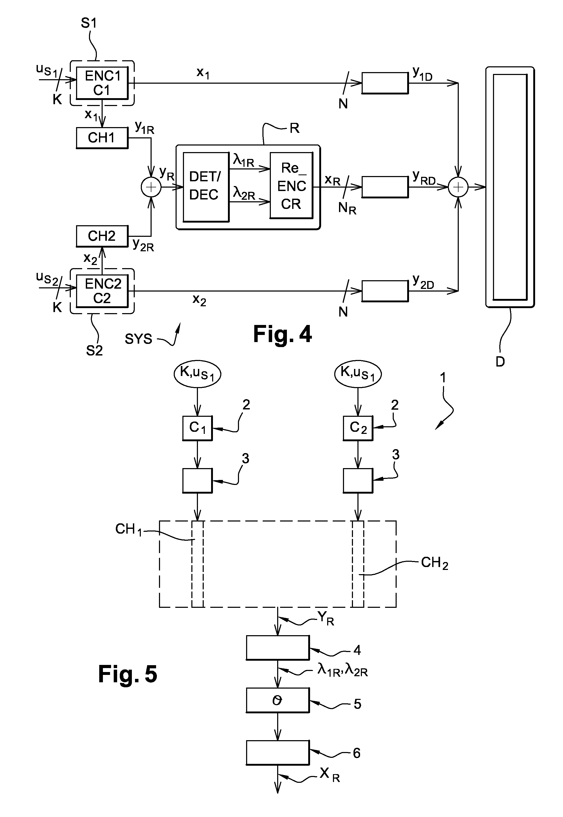
[0106]In a first embodiment, the MARC system shown in FIG. 4 has links CH1, CH2 between the sources S1, S2 and the relay R, which links are assumed to be completely reliable, in other words the links are of very good quality and decoding is practically without error.

[0107]The relay R shown in FIG. 6 performs hard decoding on the data from the two sources by means of a hard joint detector / decoder DET / DEC_d and it re-encodes the data jointly using a hard joint coder Re_ENC_d using the modulation and space time coding scheme CR.

[0108]The outputs ûS1,ûS2 from the joint detector / decoder DET / DEC_d take binary values that are used by the joint coder Re_ENC_d:

λ1R=ûS1εF2K

λ2R=ûS2εF2K

[0109]The hard joint coder Re_ENC_d makes use of two input vectors of binary values and outputs a matrix of discrete symbols SR1εχRTR×N1 where χR is a complex constellation of cardinality |χR|=2m(mεN) by applying the modulation and space time coding scheme CR:

CR:F2K×F2K→χRTR×N1

which produces the discrete symbol...

second embodiment

[0112]In a second embodiment, the MARC system shown in FIG. 4 has links CH1, CH2 between the sources S1, S2 and the relay R with Rayleigh fading. In addition, the sources have no knowledge of the link between a source and the relay. Consequently, there is a non-zero probability of the relay decoding the messages from the two sources imperfectly. Under such conditions, there is a risk of the relay propagating errors to the destination.

[0113]This embodiment makes it possible, at the destination and while performing the joint decoding, to take account of the decoding errors that arose in the relay.

[0114]In this embodiment, the relay R shown in FIGS. 7 and 8 performs soft joint detection / decoding by means of a soft joint detector / decoder DET / DEC_s in order to obtain the APPs of the information bits ({P(uk=0,1)}).

[0115]The APPs of the information bits are calculated in the form of a log likelihood ratio (LLR) defined as follows:

[λ1R]k=L(uSi,k)=[L(uSi)]k=lnP(uSi,k=1)P(uSi,k=0)k=1,…,Ki=1,2...


PUM


Abstract

A method and apparatus for transmitting a signal for a network having at least four nodes comprising two transmitters, a relay, and a receiver that are connected together by non-orthogonal links implementing a spatially-distributed network code. The method includes each transmitter delivering a code word per block of K information bits and transmitting the code words during N time slots; iterative joint detection / decoding in the relay to separate respective streams and determine, per stream, a vector representative of the received code word; jointly coding two vectors derived from the two streams to determine redundancy information representative of two code words transmitted during N time slots; transmitting, by the relay, redundancy information during N time slots; and sequencing in the relay such that the redundancy information transmitted during the N time slots corresponds to the code words transmitted during the preceding N time slots.

Description

CROSS-REFERENCE TO RELATED APPLICATIONS[0001]This Application is a Section 371 National Stage Application of International Application No. PCT / FR2010 / 051942, filed Sep. 17, 2010, which is incorporated by reference in its entirety and published as WO WO2011 / 033237 on Mar. 24, 2011, not in English.STATEMENT REGARDING FEDERALLY SPONSORED RESEARCH OR DEVELOPMENT[0002]None.THE NAMES OF PARTIES TO A JOINT RESEARCH AGREEMENT[0003]None.FIELD OF THE DISCLOSURE[0004]The field of the disclosure is that of transmitting coded data in a multiple access relay channel (MARC) network. A MARC network is a telecommunications system having at least four nodes comprising at least two transmitters, a relay, and a receiver. More precisely, the disclosure relates to network coding and involves improving the quality of data transmission, and in particular improving the performance of error-correcting decoding in a receiver.[0005]The disclosure applies particularly, but not exclusively, to transmitting data ...

Claims


Application Information

Patent Timeline
IPC IPC(8): H04B7/14H04W72/04
CPCH03M13/1102H04L1/0076H03M13/15H03M13/1515H03M13/152H03M13/23H03M13/2957H03M13/3746H03M13/3761H04B7/15521H04L1/0048H04L1/0057H04L1/06H04L25/03331H04L2001/0097H03M13/1171
Inventor HATEFI, ATOOSAVISOZ, RAPHAELBERTHET, ANTOINE
Owner ORANGE SA (FR)
Learn More