Ear microphone

a microphone and earpiece technology, applied in the field of ear microphones, can solve the problems of difficult elimination of echo and howling phenomena, and achieve the effects of clear telephone calls, unpleasant feeling, and increased voice recognition of voice-recognizing devices

Inactive Publication Date: 2013-02-07
HAEBORA
View PDF9 Cites 16 Cited by
  • Summary
  • Abstract
  • Description
  • Claims
  • Application Information

AI Technical Summary

Benefits of technology

[0033]With application of the ear microphone of the present invention constructed as describe above, two self-balanced speakers (S1, S2) of closed type are used, and the second self-balanced speaker (S2) of closed type adjusts the output of the first self-balanced speaker (S1) of closed type to eliminate the phenomenon of echo, and resistor (R6) is connected to the output terminal of the microphone in series to adjust the output, thereby inhibiting the phenomenon of howling, whereby an effect is obtained that a clear telephone call can be made even in a noisy environment.
[0034]Furthermore, by completely separating the positions of the self-balanced speaker of closed type and directional microphone, the phenomena of echo and howling can be fundamentally eliminated which result from existing speaker and microphone being positioned close to each other, and at a place where the ambient noise is severe, the voice signal provided from the ear and shielded from the external noise while the ear microphone is worn on the ear of user is provided to the external device, whereby an effect is obtained that the degree of voice recognition of the voice-recognizing device can be increased.
[0035]Furthermore, at a place where the ambient noise is weak, provides the external device with the voice signal provided from the mouth of user while being exposed to the outside, thus an effect is obtained that unpleasant feeling can be minimized that the counterpart in calling hears a twang of the caller and stuffiness can be avoided which the user may feel due to using of a shielded ear pad.
[0036]Furthermore, by positioning the output terminal of the speaker and input terminal of the microphone in the same direction and applying rubber or sound-absorbing material, an effect is obtained that the phenomena of echo and howling is blocked in a simple way, whereby a clear sound can be heard and a problem can be solved that the voice is heard by the counterpart in a low volume, thereby causing an inconvenience in telephone call.
[0037]Furthermore, since the telephone call is made through the ear, external noise can be blocked, whereby an effect is obtained that the degree of voice recognition can be enhanced in the case the that ear microphone is applied to the voice-recognizing device(navigation, robot control, voice recognition of mobile phone).

Problems solved by technology

By the way, in the case of the construction as described above, if voice-outputting direction of the speaker (2) and signal-inputting direction of the microphone (3) are commonly opposite to each other with respect to the external auditory cannel for reducing echo and oscillation, the voice coming out from the ear is input into the microphone through a long transmission path, thus there is a problem that the voice is heard by a counterpart in a low volume, hence a difficult occurs in telephone call.
In the case of such a construction, since telephone call is made using the external microphone (M2) in a quiet place, there is no concern of occurrence of the phenomenon of echo or howling, but since the voice is transmitted to the counterpart through the internal microphone (M1) in a very noisy place, it is difficult to eliminate the phenomena of echo and howling due to the integration of the speaker (S1) and microphone (M1).

Method used


Image

  • Ear microphone
  • Ear microphone
  • Ear microphone

Examples


Embodiment Construction

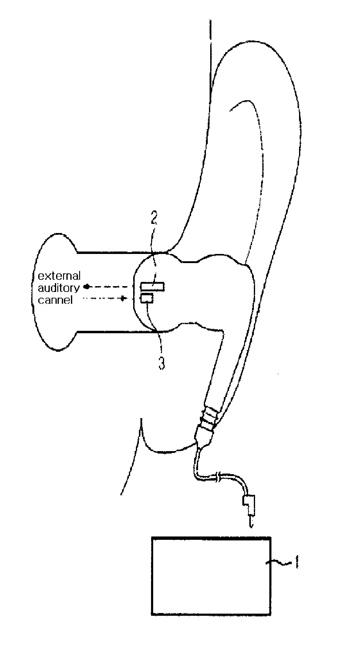
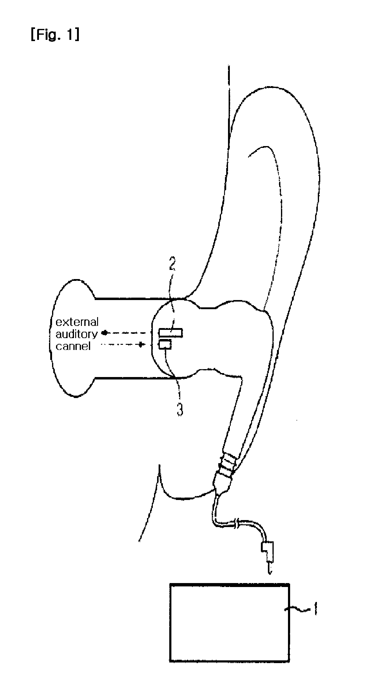
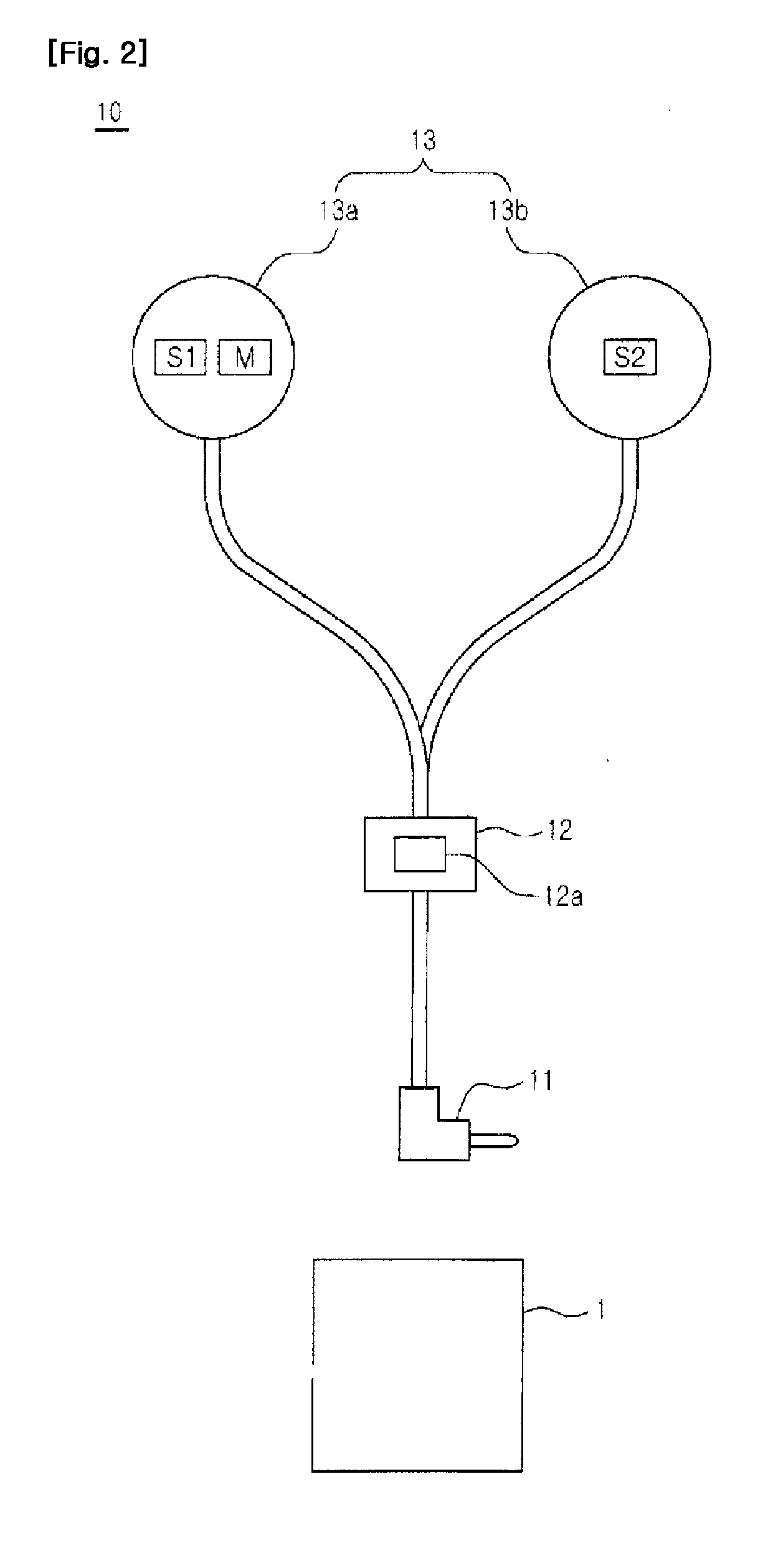
[0050]In the following, ear microphones according to preferred examples of the present invention will be described in detail with reference to the attached drawings.

[0051]However, the scope of the present invention is not limited by the examples represented in the specification of the present invention, and it should be understood that various modification and variation may be made by those having ordinary skill in the field of art to which the present invention belongs within technical concepts of the present invention and the scope of equivalent of the claims described below.

[0052]Furthermore, in describing the examples, a description will be omitted of technical content that is well known in the field of art to which the present invention belongs and does not have a direct relation with the present invention. Such omission is intended to more clearly deliver the gist of the present invention without obscuring it by omitting unnecessary description.

[0053]FIG. 4 of the attached dra...


PUM


Abstract

The present invention relates to an ear microphone for providing clear sound by preventing echo and howling phenomena by blocking external noise, and for providing an effective telephone call in a noisy environment by improving the recognition ability of a voice-recognizing device. For the ear microphone, a connector for connection to an external device, a control unit for controlling the ear microphone overall, and an earphone unit to be worn by a user for outputting or inputting voice are electrically connected to each other through cables. The earphone unit consists of a first earphone unit which includes first and second speakers wearable on the ear, a first microphone having directivity, and a second earphone unit which includes a third speaker. For the control unit, a grounding terminal and one terminal of the control unit are connected to the connector such that the other terminal is connected to the first to third speakers, and one terminal is connected to the connector such that the other terminal is connected to the first microphone. The microphone output terminal is configured to be connected to a resistor in series. The third speaker is configured as a voltage-dividing resistor on a speaker input terminal. Each voltage dividing resistor is differently designed for the first and second speakers such that the second speaker has phase characteristics that are opposite those of the first speaker, and at the same time has a voltage different from the first speaker. A negative terminal of the first speaker and a positive terminal of the second speaker connected to the speaker output terminal are connected to a volume-adjusting unit.

Description

FIELD OF THE INVENTION[0001]The present invention relates to an ear microphone, more particularly, an ear microphone which allows hearing of a clear sound to be heard by blocking the phenomena of echo and howling by blocking external noise when voice signal provided through the ear is provided to the counterpart or a voice-recognizing device is controlled and allows an effective telephone call in a noisy environment by increasing the degree of recognition of the voice-recognizing deviceDESCRIPTION OF RELATED ART[0002]In general, as illustrated in FIG. 1, an ear microphone is used by being worn on the ear of user while coupled to an external device (1) such as acoustic device or mobile phone for hearing of the sound and communication of voice signal.[0003]Referring to FIG. 1 of the attached drawings, there are provided a speaker (2) having a shape for allowing the speaker to be introduced into the ear of user and outputting the voice signal from a surface facing the ear of user and a...

Claims


Application Information

Patent Timeline
Patent Type & Authority Applications(United States)
IPC IPC(8): H04R1/10
CPCH04R1/1083H04R2420/09H04R2201/107H04R3/12
Inventor SHIN, DOO SIK
Owner HAEBORA
Why Eureka
Try Eureka