
Fiber optic distribution network for multiple dwelling units

a fiber optic distribution network and multi-dwelling technology, applied in the direction of cables, instruments, special-purpose vessels, etc., can solve the problems of consuming a lot of time and costs for installation

Active Publication Date: 2013-02-07
CORNING OPTICAL COMM LLC
View PDF4 Cites 33 Cited by
  • Summary
  • Abstract
  • Description
  • Claims
  • Application Information

AI Technical Summary

Benefits of technology

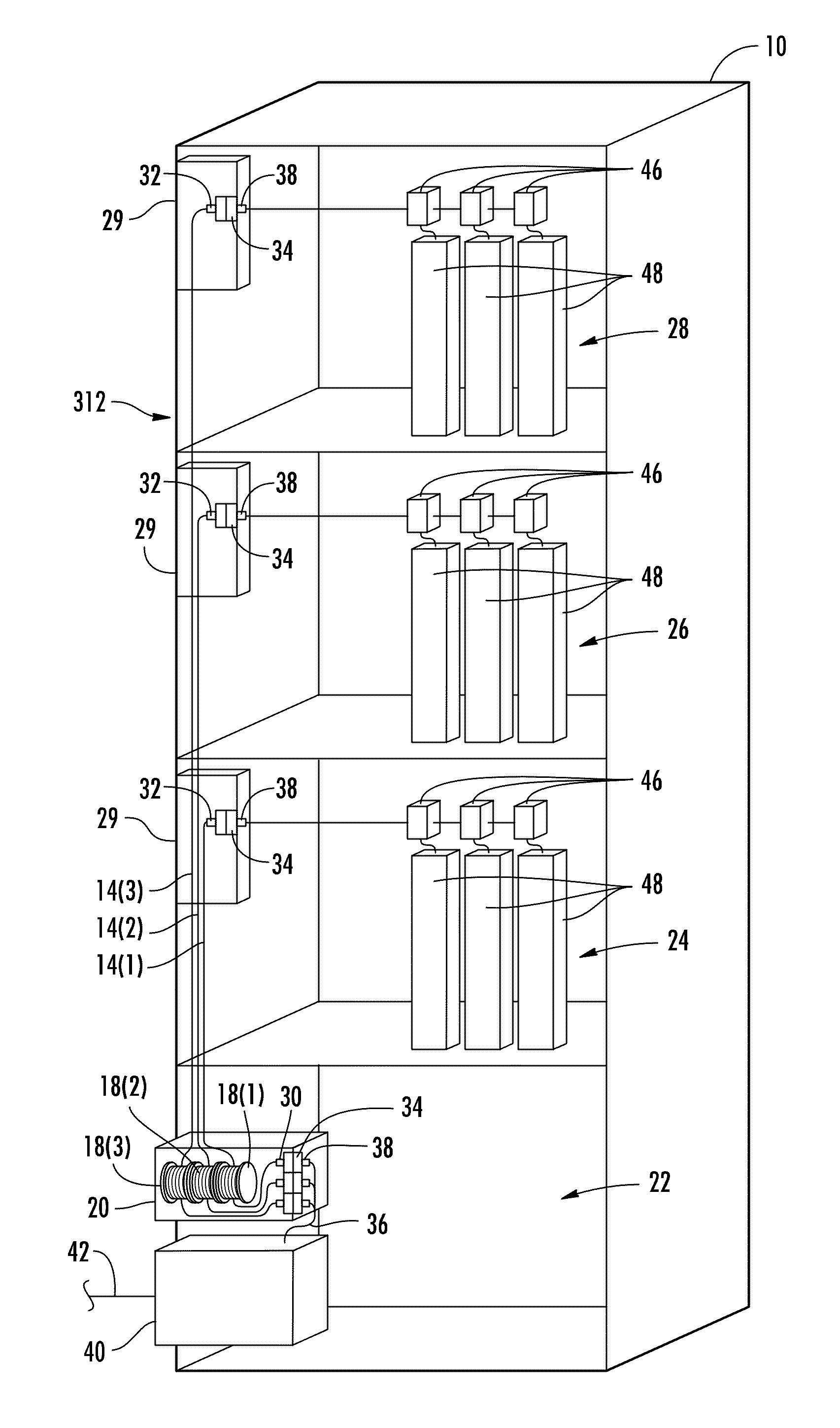
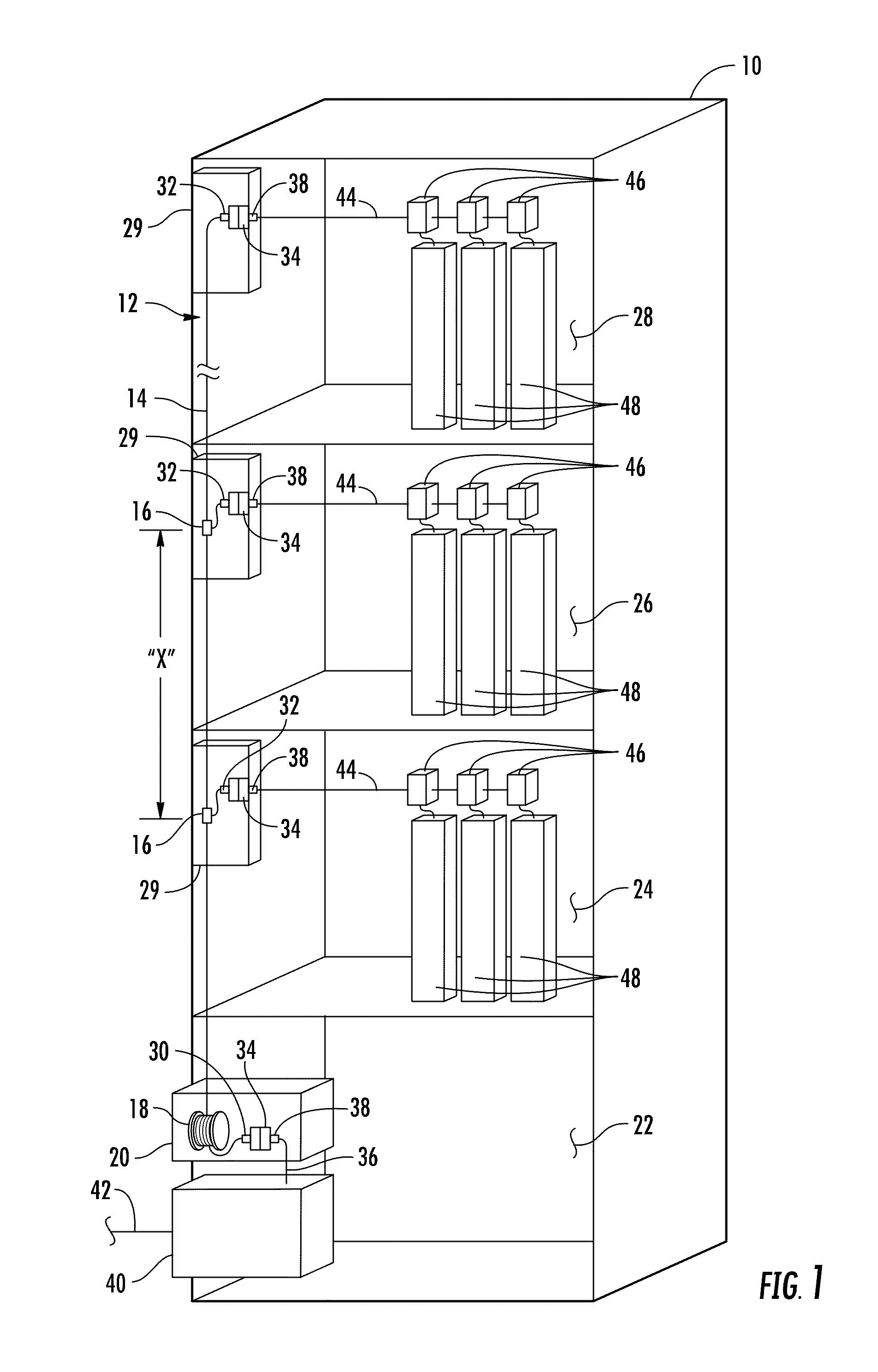
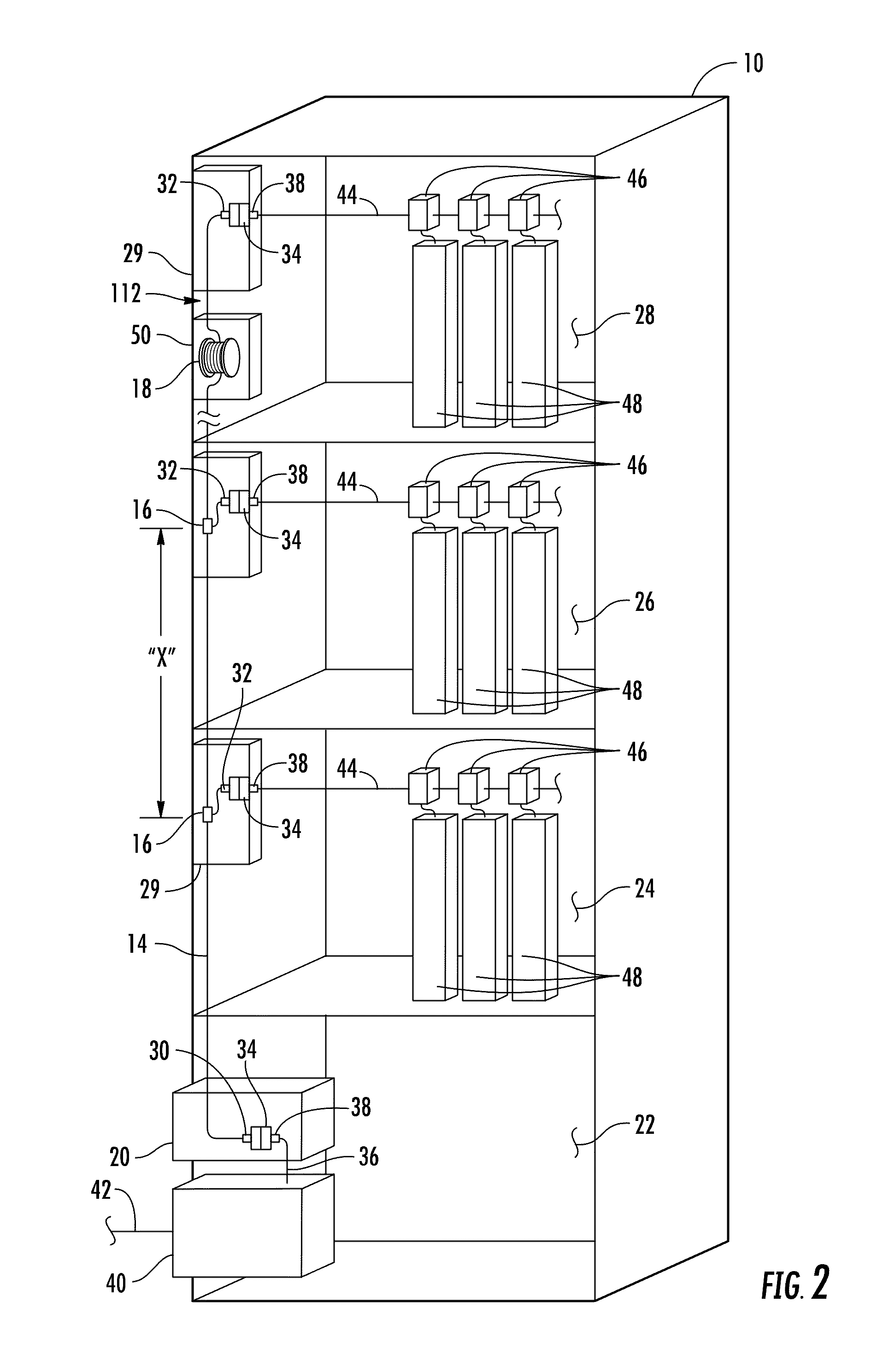
This patent describes a fiber optic network for a multiple dwelling unit (MDU) that allows for optical communication among the buildings. The network includes a riser cable that is connected to a feeder cable at the MDU. The riser cable has preset mid-span access points along its length and optical fibers that extend from these points. The first end of the riser cable is connected to a first converter located at the MDU, while the second end of the riser cable is connected to a second converter at one of the distribution levels. Payout reel is used to store the riser cable when the connectors are received, and the leader is attached to the riser cable to pay it out from the pout reel towards the distribution levels. The technical effect of this patent is to provide a convenient and efficient way to connect optical fibers between the riser cable and the distribution levels, making the network more reliable and easy to install.

Problems solved by technology

Different kind of buildings like multi dwelling units and block of apartment require complicated cabling systems which might mean that there are many separated cables, each one to connect one subscriber.
Installation of many cables which provide the connection between a main distribution point (which usually is located in the basement or in another place of the building) and the end user may cause many problems with routing through the wall or levels of the building.
As a result, such installations consume a lot of time and costs.

Method used


Image

  • Fiber optic distribution network for multiple dwelling units
  • Fiber optic distribution network for multiple dwelling units
  • Fiber optic distribution network for multiple dwelling units

Examples


Embodiment Construction

[0007]Embodiments disclosed in the detailed description include a fiber optic network for a multiple dwelling unit (MDU) comprising a riser cable preconnectorized with a first riser optical connector. The riser cable is optically connected to a feeder cable providing optical communication service to the MDU. The riser cable has one or more preset mid-span access points along the length of the riser cable. One or more optical fibers of the riser cable extend from the riser cable at the one or more preset mid-span access points and are preconnectorized with a second riser optical connector. A first adapter is located at a lower level of the MDU. The first adapter has a first end and a second end and configured to receive the first riser optical connector at the first end of the first adapter. A second adapter is located at one of the one or more distribution levels. The second adapter has a first end and a second end. A payout reel is adapted to pay out the riser cable such that the r...


PUM


Abstract

A fiber optic network for a multiple dwelling unit (MDU) is disclosed. The fiber optic network comprises a riser cable preconnectorized with a first riser optical connector. The riser cable is optically connected to a feeder cable providing optical communication service to the MDU. The riser cable has one or more preset mid-span access points along the length of the riser cable. One or more optical fibers of the riser cable extend from the riser cable at the one or more preset mid-span access points and are preconnectorized with a second riser optical connector. A payout reel is adapted to pay out the riser cable such that the riser cable extends between the lower level and at least one of the one or more distribution levels. The payout reel is adapted to store a length of the riser.

Description

CROSS REFERENCE To RELATED APPLICATIONS[0001]This application is a continuation of International Application No. PCT / US11 / 28650 filed Mar. 16, 2011, which claims the benefit of priority to U.S. application Ser. No. 61 / 314,358, filed Mar. 16, 2010, both applications being incorporated herein by reference.BACKGROUND[0002]1. Field of the Disclosure[0003]The technology of the disclosure relates to a fiber optic distribution network for indoor applications, particularly for a multiple dwelling unit. The fiber optic network can include a riser cable having tap or connection points for extending the fiber optic network to multiple floors of a multiple dwelling unit.[0004]2. Technical Background[0005]In the world of the ever-increasing need for broadband bandwidth optical cables have become the main part of telecommunication networks. Optical cables can transmit voice signals, data signals and video signals for very long distances with very high speed. Developments of optic telecommunicatio...

Claims


Application Information

Patent Timeline
Patent Type & Authority Applications(United States)
IPC IPC(8): G02B6/44G02B6/46
CPCG02B6/3897G02B6/4466G02B6/4455G02B6/4447G02B6/475G02B6/44528G02B6/44524
Inventor CASSELL, DANIEL ANDREWDAGLEY, MARK ROBERTHARVEY, GERRY JAYRODRIGUEZ, DIANAWORKS, ANTWAN JOCO'QUES
Owner CORNING OPTICAL COMM LLC
Learn More