Injection molding nozzle

US20130034621A1Active Publication Date: 2013-02-07OTTO MANNER INNOVATIONS

Image

  • Injection molding nozzle
  • Injection molding nozzle
  • Injection molding nozzle

Examples


Embodiment Construction

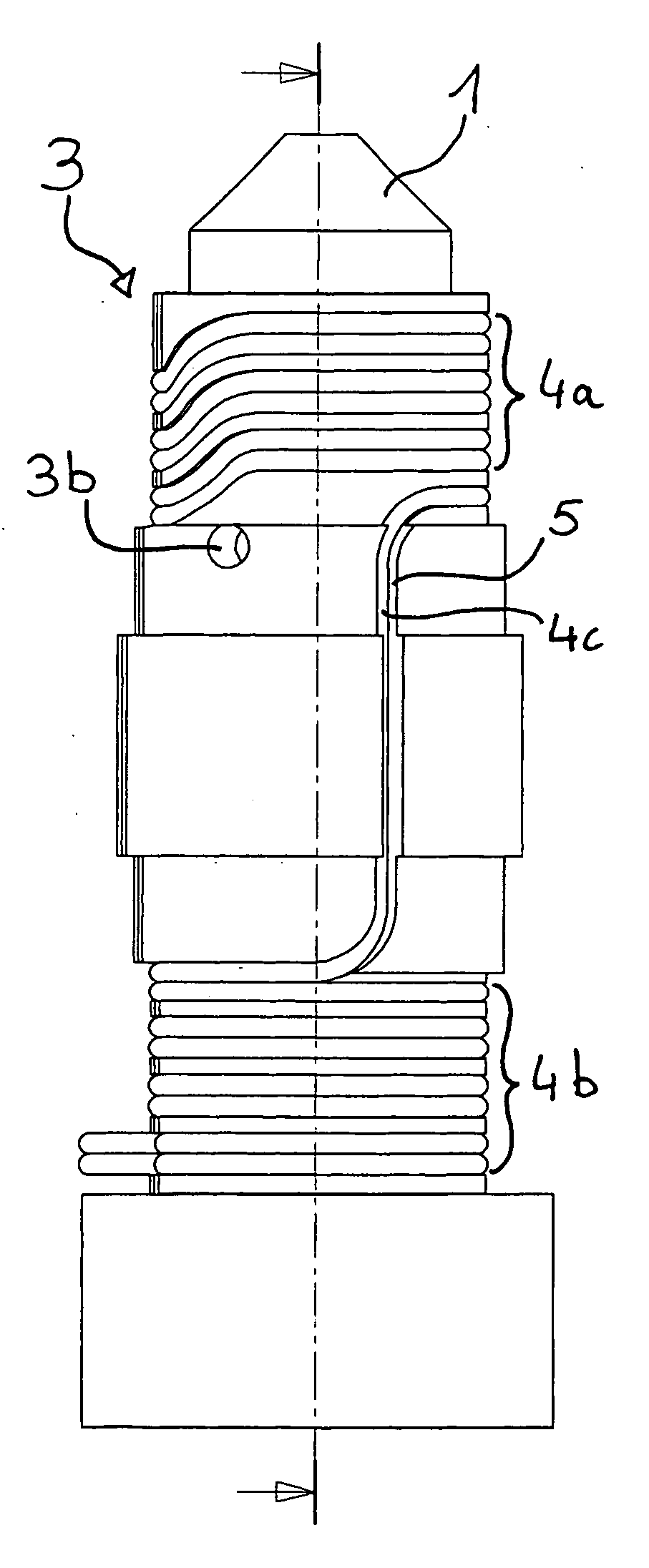
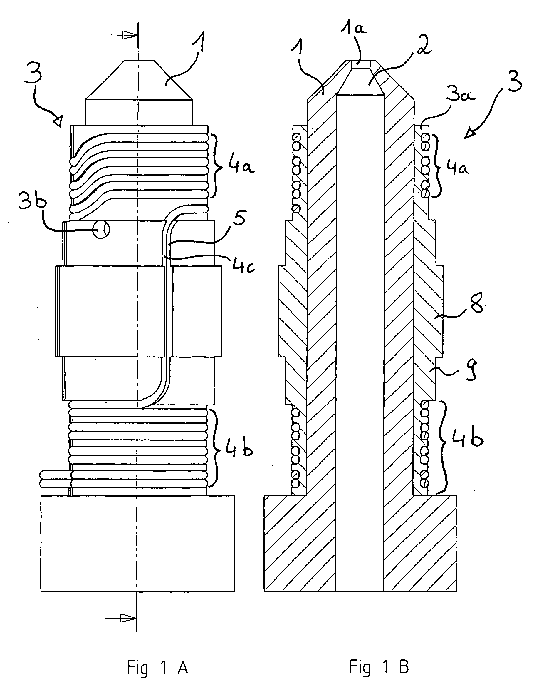
[0044]As shown in FIG. 1A and FIG. 1B, an essentially cylindrical base body 1 of an injection molding nozzle includes a channel 2 which extends essentially in axial direction of the injection molding nozzle body 1. Through the channel 2, a melt is conducted to a discharge opening 1a of the base body 1 of the injection molding nozzle.

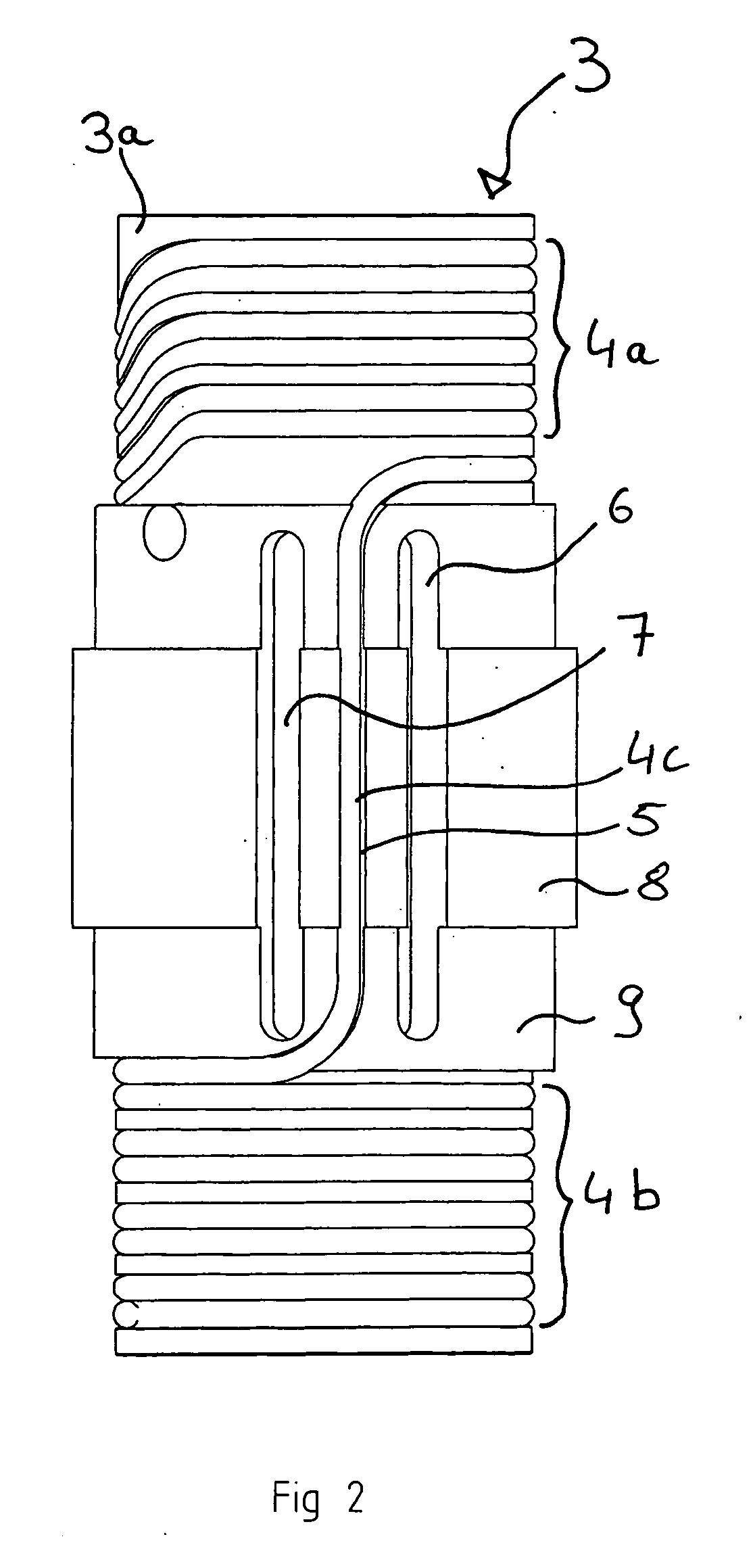
[0045]On the base body 1, a temperature control element 3 is arranged which includes a carrier sleeve 3a on which a heating coil 4a, 4b, 4c is disposed. The carrier sleeve 3a is slipped onto the base body 1 and is in good thermal contact with the base body. The heating coil comprises an upper area 4a and a lower area 4b. The two areas 4a, 4b are interconnected by means of a connecting line 4c. The connecting line extends in an axial direction of the base body 1 of the injection molding nozzle or, respectively, the carrier sleeve 3a. The windings of the upper heating coil area 4a and of the lower heating coil area 4b are arranged in grooves in such a way ...


PUM

PropertyMeasurementUnit
Temperatureaaaaaaaaaa
Areaaaaaaaaaaa
Conductionaaaaaaaaaa

Abstract

In an injection molding nozzle with an elongated base body through which a channel for conducting a melt extends and which includes a heating element for the introduction of heat into the base body with temperature controlling heating coils disposed at the two ends of the temperature control element, means are provided for reducing the introduction of heat into the base body.

Description

BACKGROUND OF THE INVENTION[0001]The invention resides in an injection molding nozzle including an elongated base body through which a channel extends for conducting a melt through the nozzle and on which an elongated temperature control element is arranged including a heating element for supplying heat to the base body and which includes heating coils at the two ends of the temperature control element.[0002]Such an injection molding nozzle has been built by the assignee and sold for many years. In the known injection molding nozzle a heating element is disposed on a sleeve which can be slipped onto a generally cylindrical base body. By means of the heating coil, the base body of the injection molding nozzle can be heated so that the melt flowing through the channel remains liquid.[0003]Since the base body of the injection molding nozzle is at its end areas always connected to an injection molding tool, heat is conducted out of the end areas of the injection molding nozzle into the ...

Claims


Application Information

Patent Timeline
07 Feb 2013
Publication
US20130034621A1
IPC
B29C45/76
CPC
B29C2045/2777; B29C45/2737
Inventors
SPULLER, SWEN