
Turbocharger

a turbocharger and turbocharger technology, applied in the direction of liquid fuel engines, bearing unit rigid support, machines/engines, etc., can solve the problems of relative low flow speed and increase the residence time of fluid (air) in the compressor diffuser, and achieve the effect of reducing the thermal conductivity of the bearing housing cover, and reducing the introduction of hea

Active Publication Date: 2018-02-20
BORGWARNER INC
View PDF16 Cites 0 Cited by
  • Summary
  • Abstract
  • Description
  • Claims
  • Application Information

AI Technical Summary

Benefits of technology

The patent describes a special type of bearing called a turbocharger, which is used to increase engine power. The invention aims to reduce the amount of heat introduced into the bearing housing. To achieve this, the bearing housing cover is made from a material with very low thermal conductivity, such as a temperature-resistant plastic. This results in a significant reduction in the amount of heat, compared to using metallic materials. The technical effect of this invention is better performance and durability of turbochargers.

Problems solved by technology

In the prior art, the temperature increase arises in that, while thermally highly conductive metallic materials are used, the relatively low flow speeds generate an increased residence time of the fluid (air) in the compressor diffuser.

Method used


Image

  • Turbocharger
  • Turbocharger
  • Turbocharger

Examples


Embodiment Construction

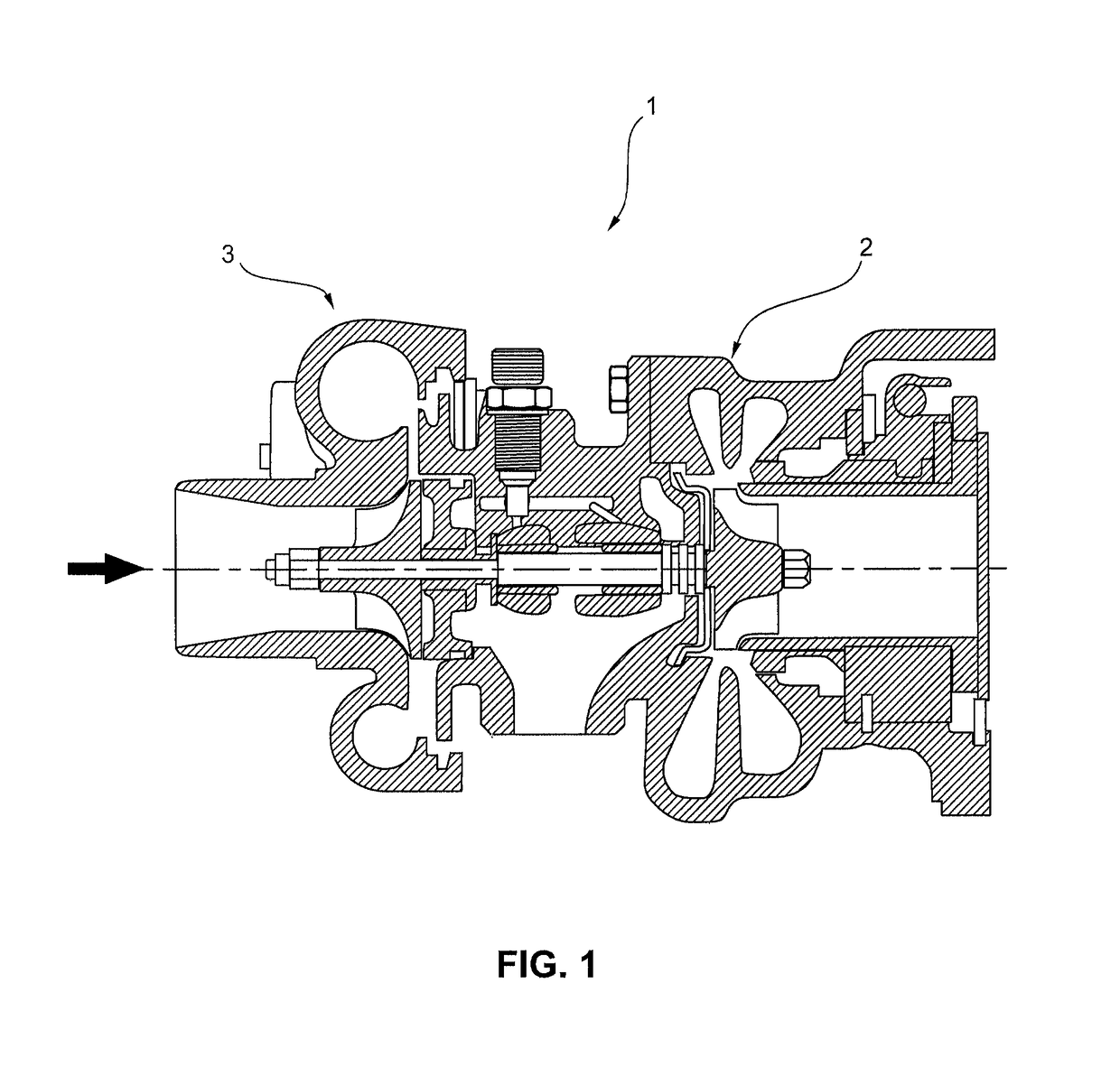
[0010]FIG. 1 shows a schematically highly simplified illustration of a turbocharger 1 which comprises a compressor 2 and a turbine 3. The turbocharger 1 self-evidently has all the other conventional components, the description of which is however not required for the explanation of the principles according to the invention and which has accordingly been omitted.

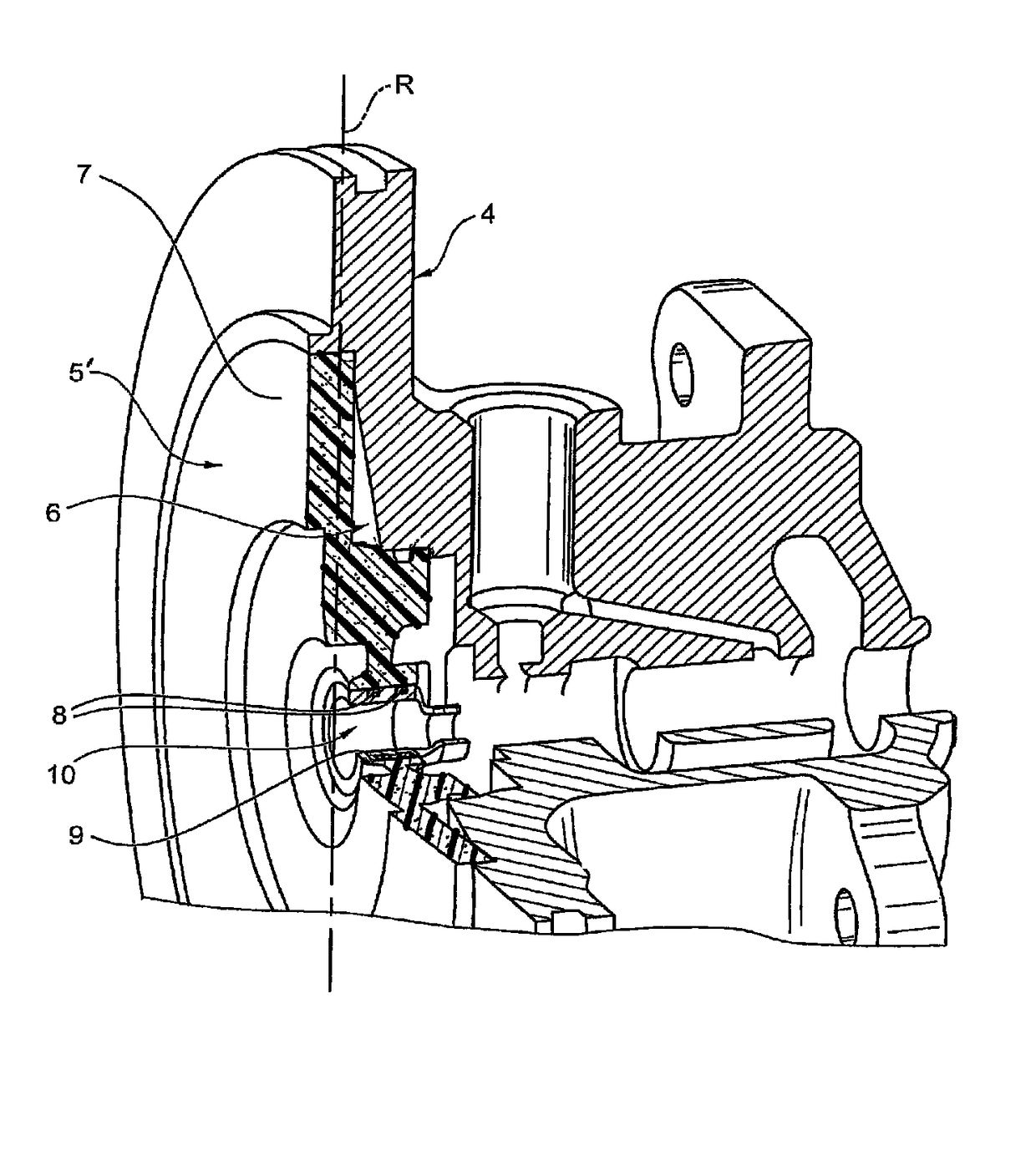
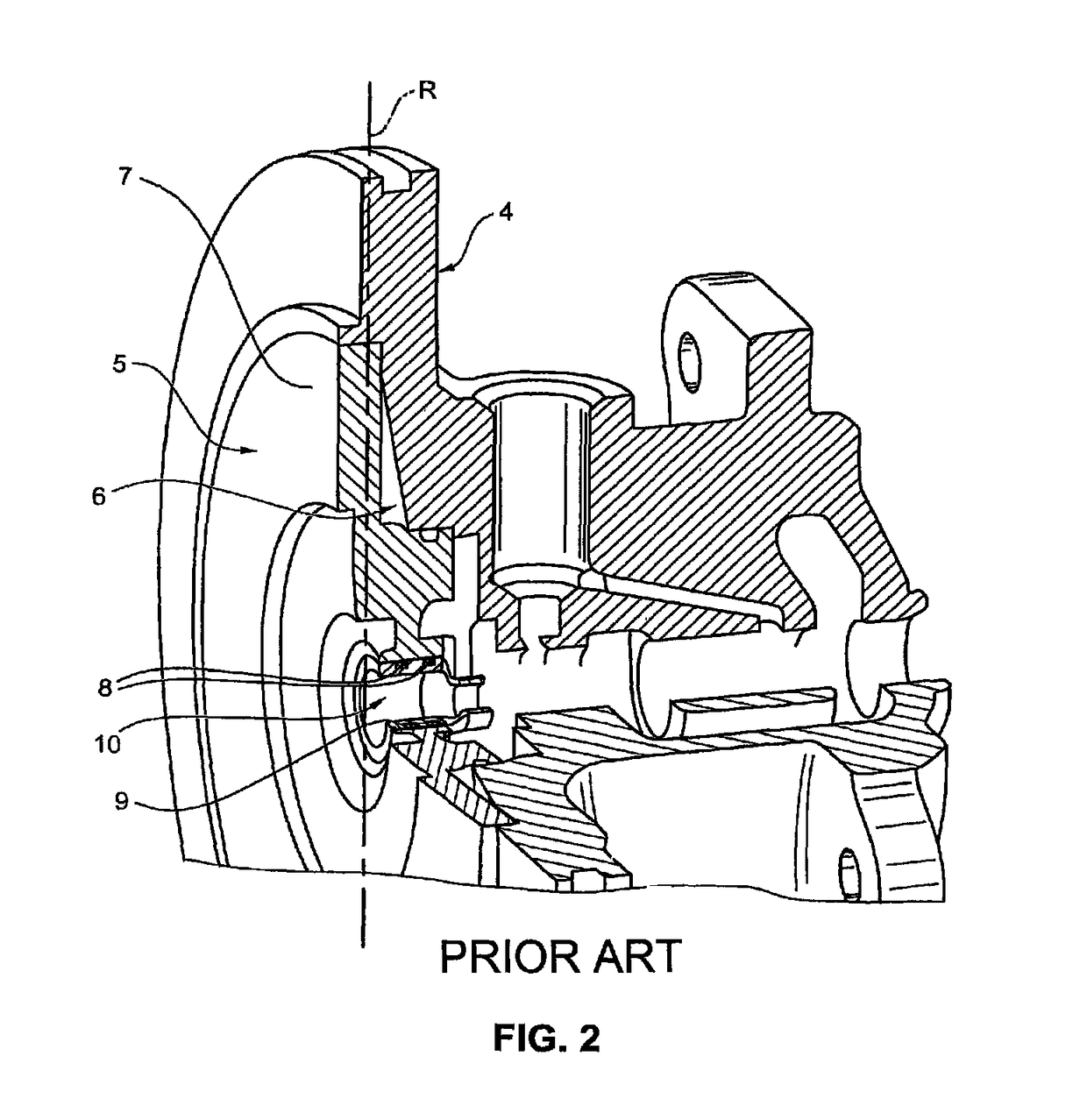
[0011]FIG. 2 illustrates an enlarged sectional view of a bearing housing 4 of a prior art turbocharger 1, which bearing housing 4 is arranged between the turbine 2 and the compressor 3 and has a metal bearing housing cover 5. Said bearing housing cover 5 is composed of metal in the prior art as shown in FIG. 2, while in the present invention it is composed of a material with low thermal conductivity as shown in FIG. 3, for example a temperature-resistant plastic, whose thermal conductivity is less than 5 W / mK. As can be seen from FIG. 3, the low thermal conductivity material bearing housing cover 5′ has been enlarged to such ...


PUM


Abstract

A turbocharger (1) in which the bearing-housing-side diffuser wall is thermally decoupled in order to reduce the heat introduction at the bearing housing cover (5). The turbocharger (1) includes a turbine (2), a compressor (3) which has a diffuser, and a bearing housing (4) which is arranged between the turbine (2) and the compressor (3) and which has the bearing housing cover (5). The bearing housing cover (5) is composed of a material with a low thermal conductivity of at most 5 W / mK, for example a temperature-resistant plastic.

Description

BACKGROUND OF THE INVENTIONField of the Invention[0001]The invention relates to a turbocharger.Description of the Related Art[0002]A generic turbocharger is known from EP 1 256 703 B1.[0003]Turbochargers of said type are used in internal combustion engines in order to increase the engine characteristic values such as power and torque and to reduce exhaust-gas emissions and specific fuel consumption. At low circumferential speeds of the compressor wheel, a temperature increase of the compressor air flow occurs at the bearing-housing-side housing wall of the compressor diffuser. Since the metal bearing housing constitutes the connecting element between the metal turbine housing and the metal compressor housing, considerable internal heat transfer takes place from the turbine side to the compressor side. In the prior art, the temperature increase arises in that, while thermally highly conductive metallic materials are used, the relatively low flow speeds generate an increased residence...

Claims


Application Information

Patent Timeline
Patent Type & Authority Patents(United States)
IPC IPC(8): F02C6/12F01D25/16
CPCF01D25/162F05D2300/5024F05D2220/40F01D25/16F01D25/24F02B39/00F16C35/04
Inventor LISCHER, THOMAS
Owner BORGWARNER INC
Learn More