Injector for dental implants

a technology for injecting dental implants and implants, which is applied in the fields of dental implants, teeth filling, medical science, etc., can solve the problems of high cost of natural or artificial bone graft material, damage to surrounding teeth and bone, and leakage of bone graft material from the drilled hole, etc., to achieve gentle curvature, easy to make, and easy to injected

Inactive Publication Date: 2013-02-07
SONG YOUNG WAN
View PDF7 Cites 7 Cited by
  • Summary
  • Abstract
  • Description
  • Claims
  • Application Information

AI Technical Summary

Benefits of technology

[0044]According to the embodiments of the present invention, because the main body and the piston, which form the injector, have a gentle curvature, the injector may easily approach an operation region in a mouth, and thus, the leading end of the injector can be accurately positioned at the hole, and the contents in the injector can be easily injected into the hole without leaking to the outside.
[0045]Moreover, according to the embodiments of the present invention, because the packing, which is formed in the leading end of the piston and corresponds to the protruding part, is made of a flexible material such as silicon or rubber which can be elastically transformed, the present invention makes the contents put inside the main body and the protruding part be injected to prevent the contents from being wasted unnecessarily.
[0046]Moreover, according to the embodiments of the present invention, because the main body and the piston are formed to have a gentle curvature, the main body and the piston may be easily made by using the scheme of the injection molding, and the manufacturing cost may be saved by making the structure of the main body and the piston simple.
[0047]Therefore, according to the embodiment of the present invention, the injector for dental implants may be manufactured with a low cost and may be uses as a disposable product.

Problems solved by technology

General prosthetic appliances or dentures damage a surrounding tooth and bone.
Because a natural or artificial bone graft material is considerably high cost, a doctor handling the bone graft material pays particular attention to handling the bone graft material.
However, when the general syringe is used, if a size of a leading end of a protruding part of the syringe is greatly larger or smaller than that of the drilled hole, the bone graft material may leak from the drilled hole, or may be not jetted in the sufficient depth of inside the drilled hole.
Therefore, a close degree between the piston and an inner wall of the syringe is low, and thus, a pressure to jet the bone graft material is not sufficiently formed.
However, even if the process of sterilizing the syringe is performed, because it is impossible to perfectly sterilize the syringe, it is preferable to use a disposable syringe.
However, in the syringe according to the patent reference 1, because the syringe barrel 1, the piston 2 and the second piston 3 has to be respectively manufactured to be combined, a structure of the syringe is complex, and thus, a manufacturing process increase and a manufacturing cost increase, thereby the syringe according to the patent reference 1 being unsuitable for the disposable syringe.
However, in the patent reference 2, because only the soft rubber 16 is replaced to be used, and the injection tube 10 and the other parts of the push bar 11 is reused, a lot of effort and a lot of money are need during a sterilization process.
Therefore, when an injection molding for manufacturing the injection tube 10 is performed, a level of difficulty increases, thereby operating efficiency being reduced.
Therefore, it is difficult to make a disposable syringe by applying the patent reference 2.

Method used


Image

  • Injector for dental implants
  • Injector for dental implants
  • Injector for dental implants

Examples


Embodiment Construction

[0055]Reference will now be made in detail to the exemplary embodiments of the present invention, examples of which are illustrated in the accompanying drawings. Wherever possible, the same reference numbers will be used throughout the drawings to refer to the same or like parts. Hereinafter, the injector of dental implants according to the embodiments of the present invention will be described in detail with reference to the accompanying drawings.

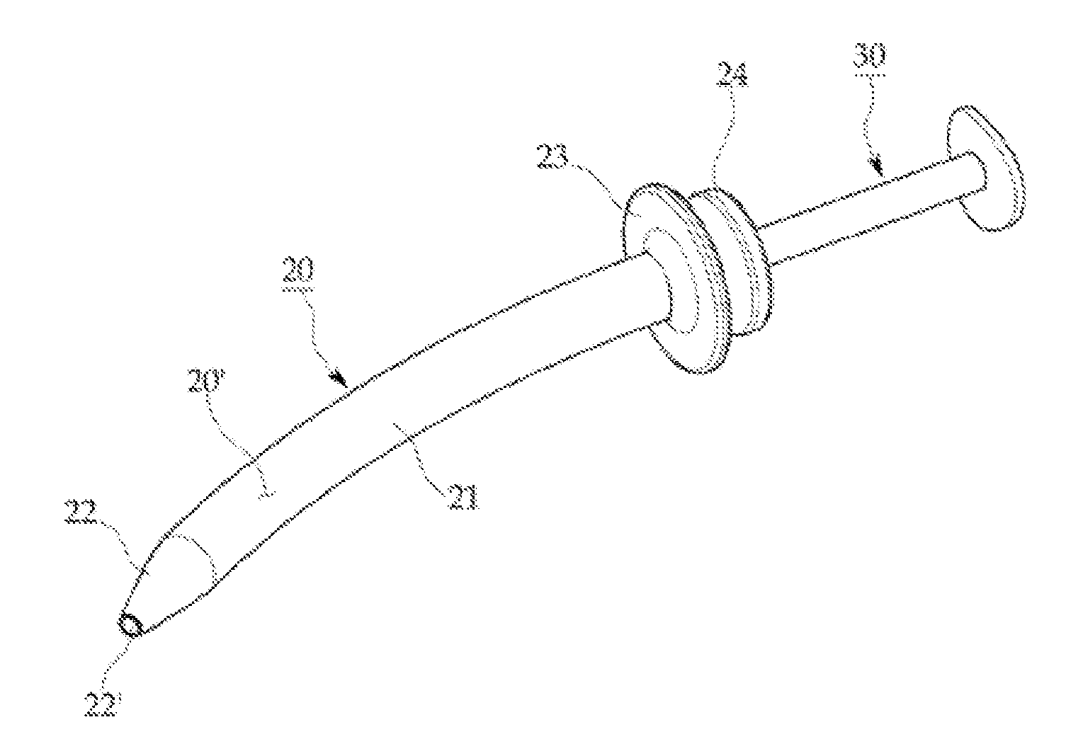
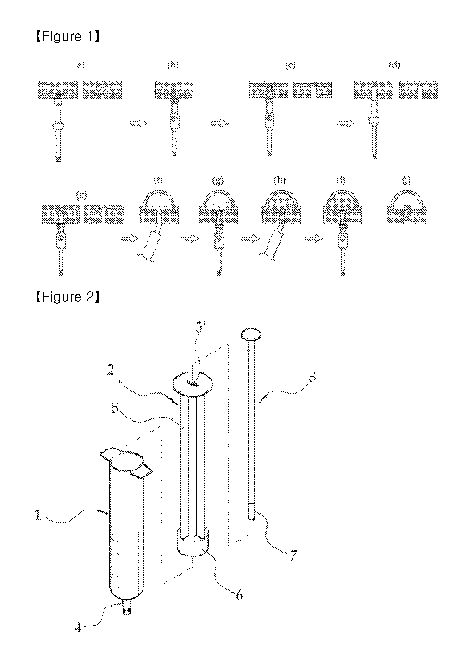
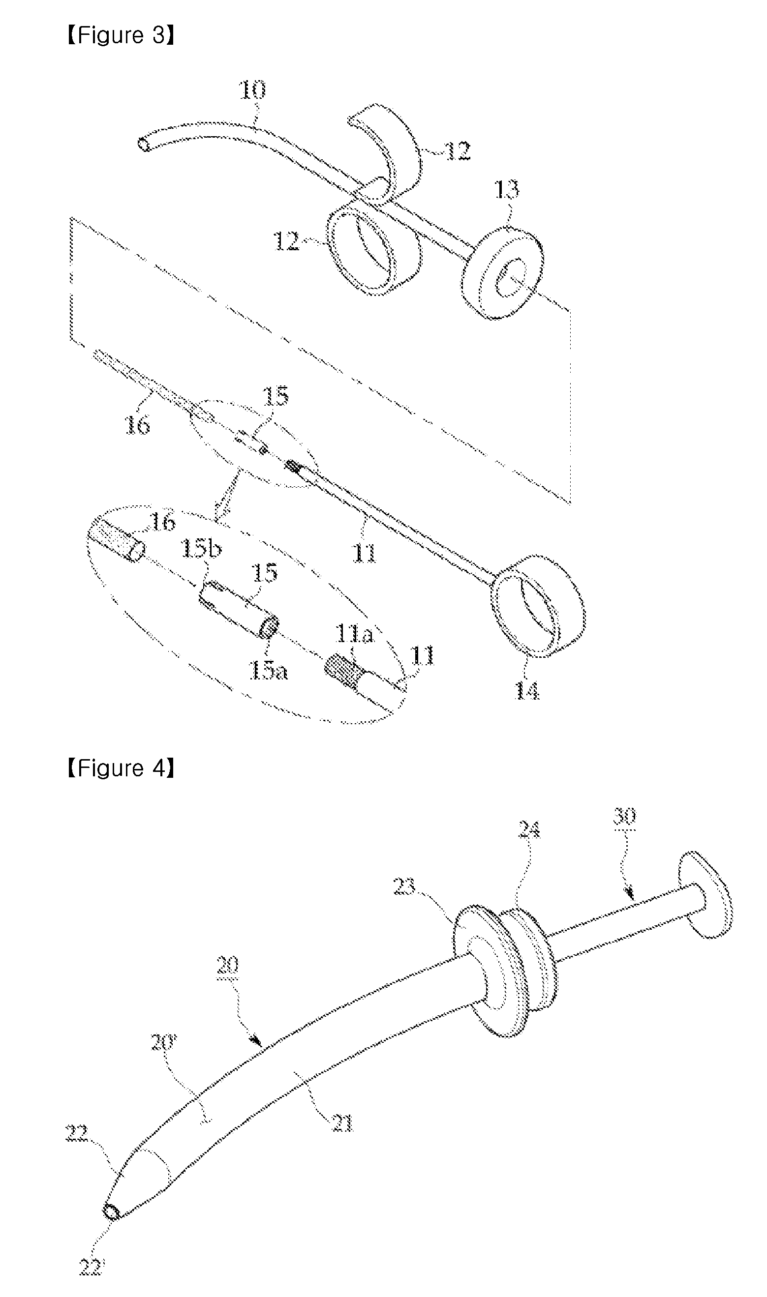
[0056]FIG. 4 is a perspective view of an injector for dental implants according to an embodiment of the present invention, FIG. 5 is an exploded perspective view of the injector for dental implants shown in FIG. 4 and FIG. 6 is an exemplary diagram illustrating an operation of the injector for dental implants according to an embodiment of the present invention.

[0057]The injector for dental implants according to an embodiment of the present invention, as shown in FIG. 4, includes a main body 20 the entirety of which is formed so as to have ...


PUM


Abstract

The present invention relates to an injector for dental implants, comprising: a main body which is formed into an annular tube, the entirety of which is formed so as to have a gentle curvature, and the center of which has a through-hole; and a piston inserted into the through-hole of the main body so as to press the contents in the main body, wherein the piston is made of a flexible material which can be elastically transformed, and a packing is coupled to the leading end of the piston. The main body and the piston of the injector for dental implants according to the present invention have gentle curvatures, and therefore the leading end of the injector can be accurately positioned at a hole formed in the bone of a patient, and the contents in the injector can be easily injected into the hole formed in the bone without leaking to the outside.

Description

TECHNICAL FIELD[0001]The present invention relates to an injector for dental implants, and more particularly, to an injector for dental implants which injects a bone graft material so as to reinforce an artificial dental root placed part during dental implants operation.BACKGROUND ART[0002]The implant means a replacement which replaces a lost human tissue, but in dentist, the implant means that an artificially made dental root, that is, a tooth root is transplanted.[0003]This implant is a high tech operation which implants an artificial dental root made of titanium, which does not show an adverse reaction to the human tissue, or the like in a bone where a tooth falls out, and then, fixes an artificial tooth to restore a function of a tooth.[0004]General prosthetic appliances or dentures damage a surrounding tooth and bone. However, the implant does not damages a surrounding tooth, and because a function and a shape of the implant are the same as that of a natural tooth and does not ...

Claims


Application Information

Patent Timeline
Patent Type & Authority Applications(United States)
IPC IPC(8): A61C13/38A61C8/00
CPCA61C8/0006A61C8/0092A61C5/062A61C5/62
Inventor SONG, YOUNG WAN
Owner SONG YOUNG WAN
Why Eureka
Try Eureka