Techniques for percutaneous mitral valve replacement and sealing
What is Al technical title?
Al technical title is built by PatSnap Al team. It summarizes the technical point description of the patent document.
a technology of mitral valve and percutaneous mitral valve, applied in the field of valve replacement, can solve the problems of reducing cardiac output and increasing total stroke volum
Active Publication Date: 2013-02-07
CARDIOVALVE LTD
View PDF32 Cites 332 Cited by
Summary
Abstract
Description
Claims
Application Information
AI Technical Summary
This helps you quickly interpret patents by identifying the three key elements:
Problems solved by technology
Method used
Benefits of technology
[0125]In an application, coupling the prosthetic valve support to the native valve in a manner that allows the native valve to continue to function, at least in part, includes coupling the prosthetic valve support to the native valve in a manner that allows the heart of the subject to support the subject for longer than 5 minutes after the prosthetic valve support is coupled to the native valve of the subject.
[0126]In an application, coupling the prosthetic valve support to the native valve in a manner that allows the native valve to continue to function, at least in part, includes coupling the prosthetic valve support to the native valve in a manner that allows the heart of the subject to support the subject for longer than 1 hour after the prosthetic valve support is coupled to the native valve of the subject.
Problems solved by technology
Regurgitation of blood from the ventricle into the atrium results in increased total stroke volume and decreased cardiac output, and ultimate weakening of the ventricle secondary to a volume overload and a pressure overload of the atrium.
Method used
Image
Click on the blue label to locate the original text in one second.
Reading with bidirectional positioning of images and text.
Examples
Embodiment Construction
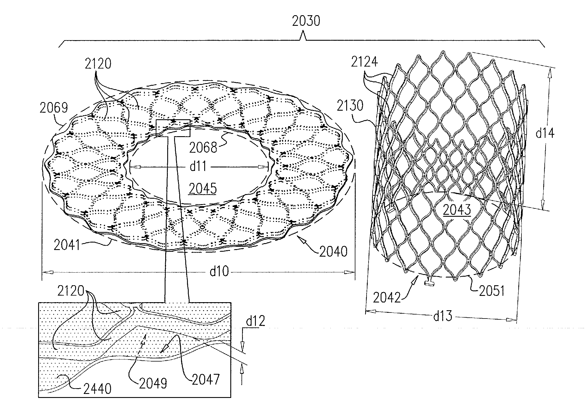
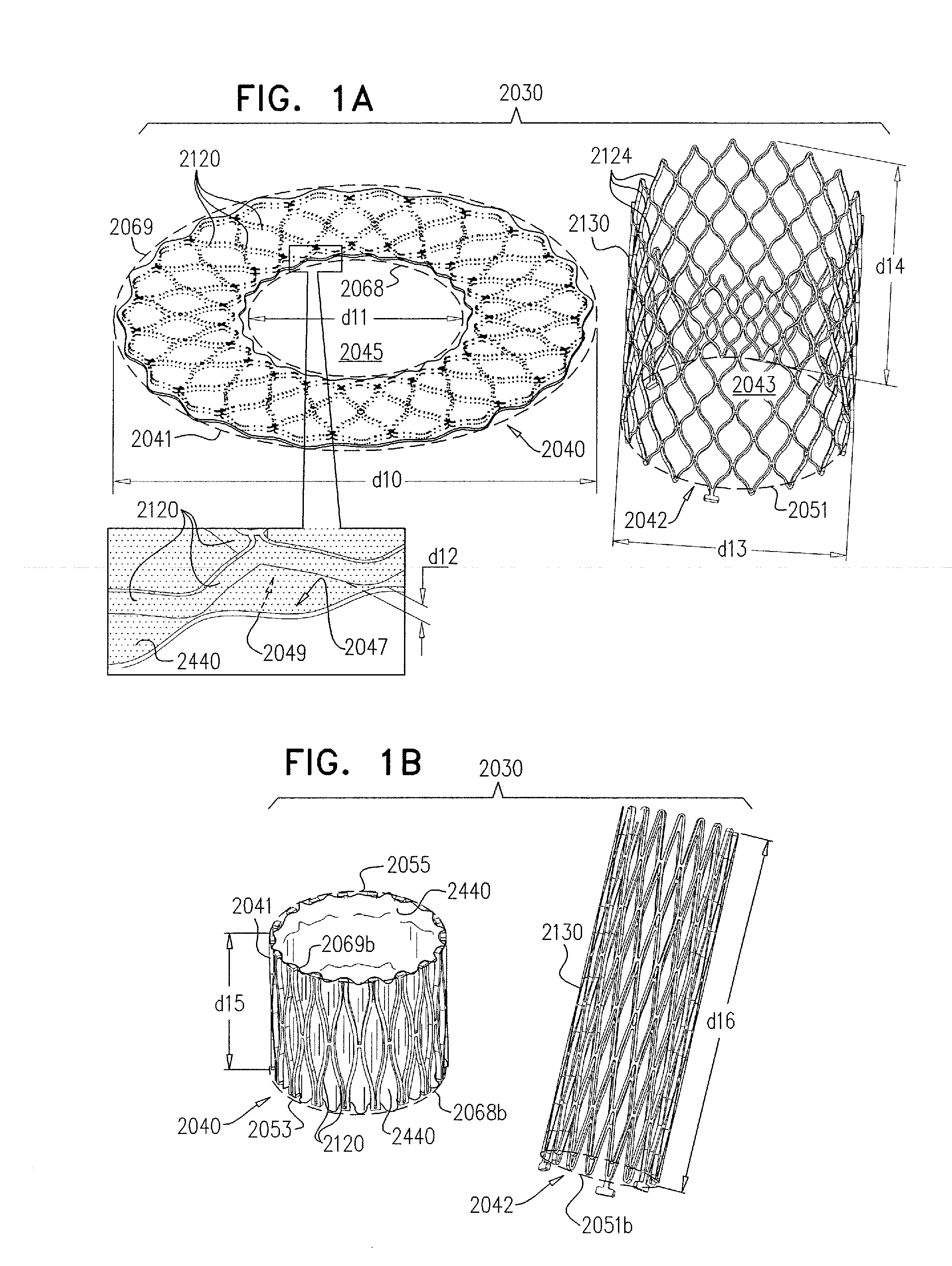
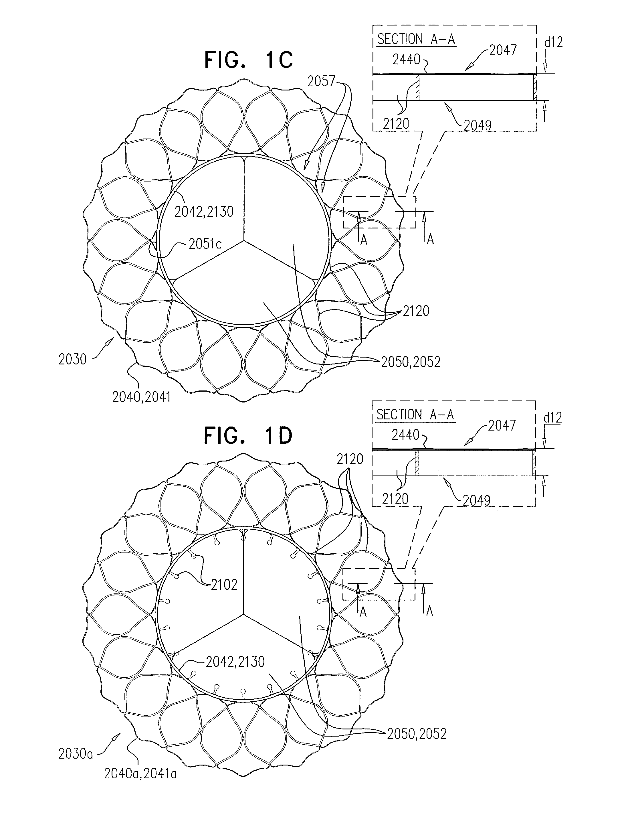
[0372]Reference is made to FIGS. 1A-D, which are schematic illustrations of an implant 2030, comprising a prosthetic valve support 2040, and a prosthetic valve 2042, in accordance with some applications of the invention. Implant 2030 is configured to be implanted at a native heart valve of a subject, such as the mitral valve 2024 of the subject.
[0373]FIG. 1A shows support 2040 and prosthetic valve 2042 of implant 2030 in respective fully uncompressed configurations thereof. Support 2040 comprises an upstream support portion 2041, which is shaped to define an opening 2045, and configured to be placed against an upstream side of the native valve of the subject (e.g., against an atrial side of the mitral valve of the subject, such as against the annulus of the mitral valve of the subject). Typically, upstream support portion 2041 is configured to be placed against the upstream side of the native valve such that the entire of opening 2045 is disposed above (i.e., upstream and within a p...
PUM
Abstract
Apparatus is described for use with a native heart valve of a subject, the apparatus including (1) a prosthetic valve support, comprising an upstream support portion, the upstream support portion having (a) a compressed configuration and an uncompressed configuration in which the upstream support portion has an inner perimeter that defines an opening; and (2) a prosthetic valve, advanceable into the opening defined by the upstream support portion, and intracorporeally couplable to the upstream support portion by being expanded within the opening defined by the upstream support portion, the apparatus being configured such that, when the prosthetic valve is expanded within the opening defined by the upstream support portion, the expansion of the prosthetic valve is restricted by the inner perimeter of the upstream support portion, without causing the prosthetic valve support to apply a radially-expansive force to the native annulus. Other embodiments are also described.
Description
CROSS-REFERENCES TO RELATED APPLICATIONS[0001]The present application is related to, and claims priority from, U.S. Provisional Application 61 / 515,372 filed Aug. 5, 2011, U.S. Provisional Application 61 / 525,281 filed Aug. 19, 2011, U.S. Provisional Application 61 / 537,276, filed Sep. 21, 2011, U.S. Provisional Application 61 / 555,160, filed Nov. 3, 2011, and U.S. Provisional Application 61 / 588,892, filed Jan. 20, 2012, which are incorporated herein by reference.FIELD OF THE INVENTION[0002]Some applications of the present invention relate in general to valve replacement. More specifically, some applications of the present invention relate to prosthetic valves for replacement of a cardiac valve.BACKGROUND[0003]Ischemic heart disease causes regurgitation of a heart valve by the combination of ischemic dysfunction of the papillary muscles, and the dilatation of the ventricle that is present in ischemic heart disease, with the subsequent displacement of the papillary muscles and the dilata...
Claims
Application Information
Patent Timeline
Application Date:The date an application was filed.
Publication Date:The date a patent or application was officially published.
First Publication Date:The earliest publication date of a patent with the same application number.
Issue Date:Publication date of the patent grant document.
PCT Entry Date:The Entry date of PCT National Phase.
Estimated Expiry Date:The statutory expiry date of a patent right according to the Patent Law, and it is the longest term of protection that the patent right can achieve without the termination of the patent right due to other reasons(Term extension factor has been taken into account ).
Invalid Date:Actual expiry date is based on effective date or publication date of legal transaction data of invalid patent.
Patent Type & Authority Applications(United States)