Switchable diffractive accommodating lens

a technology of diffractive accommodating and swinging lens, which is applied in the field of swinging diffractive accommodating lens, can solve the problems of reducing the contrast of each image, unable to be relied on for consistent operation of accommodating device, and contributing to halo and glare perception, so as to improve image contrast and reduce halo and glare.

Inactive Publication Date: 2013-02-07
PORTNEY VALDEMAR
View PDF12 Cites 81 Cited by
  • Summary
  • Abstract
  • Description
  • Claims
  • Application Information

AI Technical Summary

Benefits of technology

[0048]In case of diffractive accommodating lens of this invention, light utilizes much more efficiently, the total amount of light used to form in-focus images at certain aperture size exceeds the total amount of light entering the lens within the same aperture size. The reason is that both in-focus images form sequentially by redirecting some light from in-focus image at one image position to in-focus image at another image position. It is possible that the diffractive accommodating lens of this also invention also split light between the images at two image positions simultaneously but the use of light for in-focus image is higher than in multifocal diffractive lens because the some or all amount of light is redirected inform in-focus image at one image position to the in-focus image in another image position. This improves image contrast and reduces halo and glare as compared with multifocal diffractive optic.

Problems solved by technology

All other ocular elements involved in the accommodation such as zolules, capsular bag and the crystalline lens itself are highly age and individual condition dependent and can't be relied on for consistent operation of accommodating devices.
Multifocal diffractive lens is also used to provide two image positions for far and near vision for Presbyopia treatment but the issue with this type of design is that in-focus image at each image position includes out-of-focus image resulted in blur that reduces each image contrast and contributing to halo and glare perception.

Method used


Image

  • Switchable diffractive accommodating lens
  • Switchable diffractive accommodating lens
  • Switchable diffractive accommodating lens

Examples


Embodiment Construction

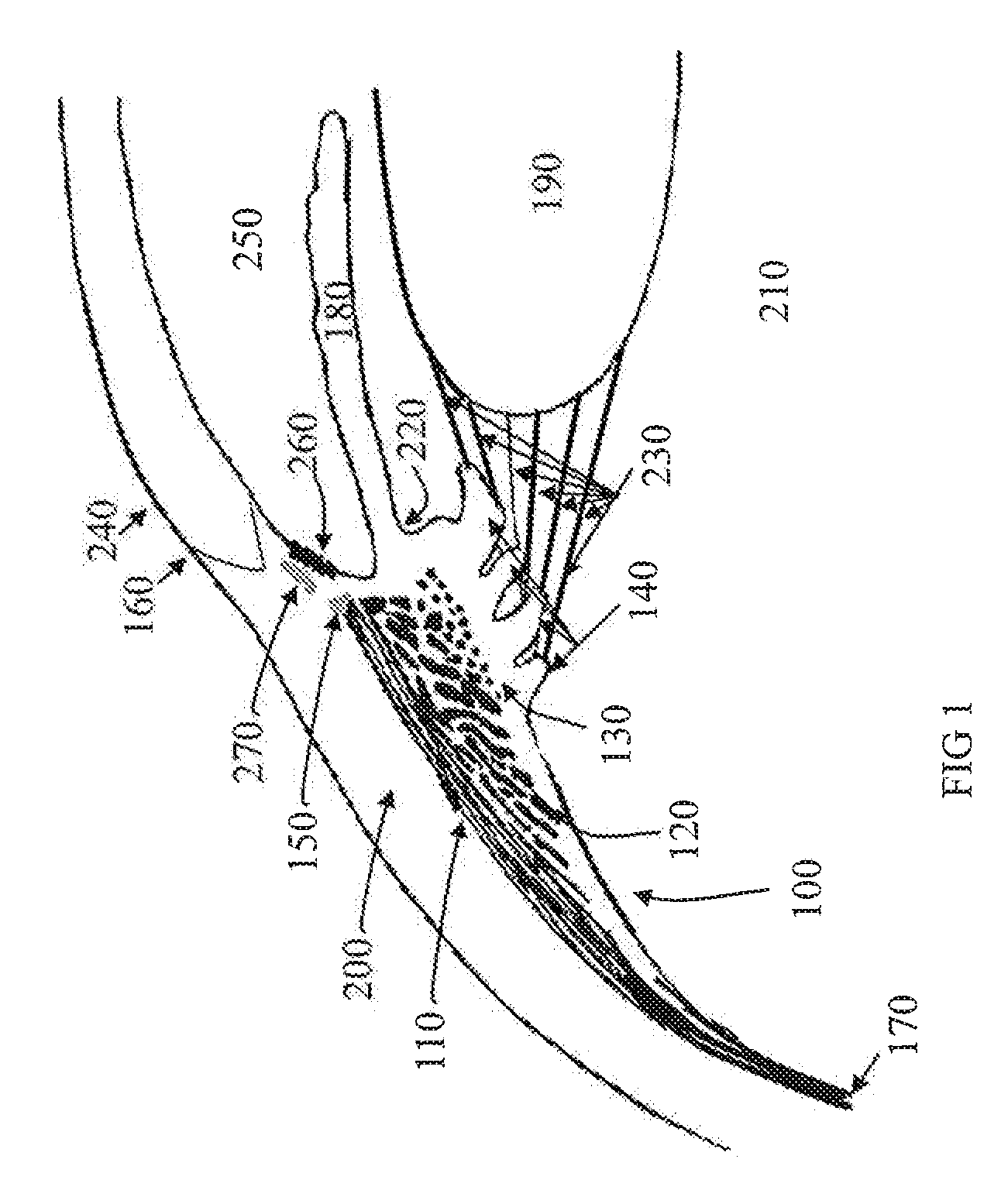
[0076]FIG. 1 illustrates a portion of eye anatomy related to the accommodation process. The ciliary body 100 has three basic functions: aqueous production and removal, accommodation, and the formation of vitreous mucopolysaccharide. The ciliary muscle initiates accommodating process and situates inside the ciliary body 100. The ciliary muscle contains three types of fibers: longitudinal 110, radial 120 and circular 130 fibers.

[0077]The accommodation function is the primary objective of this invention and the first order is to describe the ciliary muscle including their anatomy.

[0078]The ciliary body 100 is somewhat triangular in meridional sections and present circumferentially around the internal surface of the eye globe. It is narrower nasally (4.5-5.2 mm) than temporally (5.6-6.3 mm). The anterior margin of the ciliary body 100 is at the scleral spur 150 is about 1.5 mm posterior to the corneal limbus 160 in the horizontal meridian and 2 mm posterior in the vertical meridian. Cor...


PUM


Abstract

A lens in accordance with the present invention includes an accommodating cell having two chambers with at least one chamber filled with optical fluid with the refractive index matching the refractive index of the accommodating element separating them. The accommodating element has a diffractive surface with surface relief structure that maintains its period but changes its height due a pressure difference between the chambers to redirect most of light that passes through the lens between different foci of far and near vision. The invention also includes a sensor cell that directly interacts with the ciliary muscle contraction and relaxation to create changes in pressure between the accommodating cell chambers that results in changing surface relief structure height and the lens accommodation.

Description

FIELD OF THE INVENTION[0001]The present invention relates generally to a diffractive lens that creates an image at different positions sequentially by the change in magnitude of the surface relief structure height at its diffractive surface, and more particularly to a diffractive ophthalmic lens that changes surface relief structure height at one of its surfaces to provide distance and near foci, and even more particularly to diffractive accommodating lens that changes surface relief structure height under the action of ciliary muscle.BACKGROUND OF THE INVENTION[0002]The diffractive lens of this disclosure can be applied outside or within ophthalmic application. In later case the lens is called ophthalmic lens. Ophthalmic lens in this disclosure is defined as a lens suitable for placement outside the eye such as spectacles or contact lenses or inside the eye such as aphakic and phakic intraocular lenses placed in posterior or anterior eye chamber and also included are less common vi...

Claims


Application Information

Patent Timeline
Patent Type & Authority Applications(United States)
IPC IPC(8): A61F2/16G02C7/04G02C7/02
CPCG02C7/04G02C7/085A61F2/142A61F2/1635A61F2/1654G02C2202/20A61F2/14A61F2250/0002
Inventor PORTNEY, VALDEMAR
Owner PORTNEY VALDEMAR
Why Eureka
Try Eureka