Medical device lock mechanism

Active Publication Date: 2013-02-07
SEASPINE
View PDF3 Cites 38 Cited by
  • Summary
  • Abstract
  • Description
  • Claims
  • Application Information

AI Technical Summary

Benefits of technology

[0006]In accordance with one aspect of the present invention, there is provided a medical device comprising (a) an implant body including a plurality of segments interconnected so as to assume a straightened state and a flexed deployed state, the implant body formed with at least two engagement elements, each of at least two different segments having an engagement element; and (b) an elongated locking element anchored at one segment of said implant body, the locking element having at least two projections corresponding to the at least two enga

Problems solved by technology

If the implant were to open after deployment, it could damage

Method used


Image

  • Medical device lock mechanism
  • Medical device lock mechanism
  • Medical device lock mechanism

Examples


Example

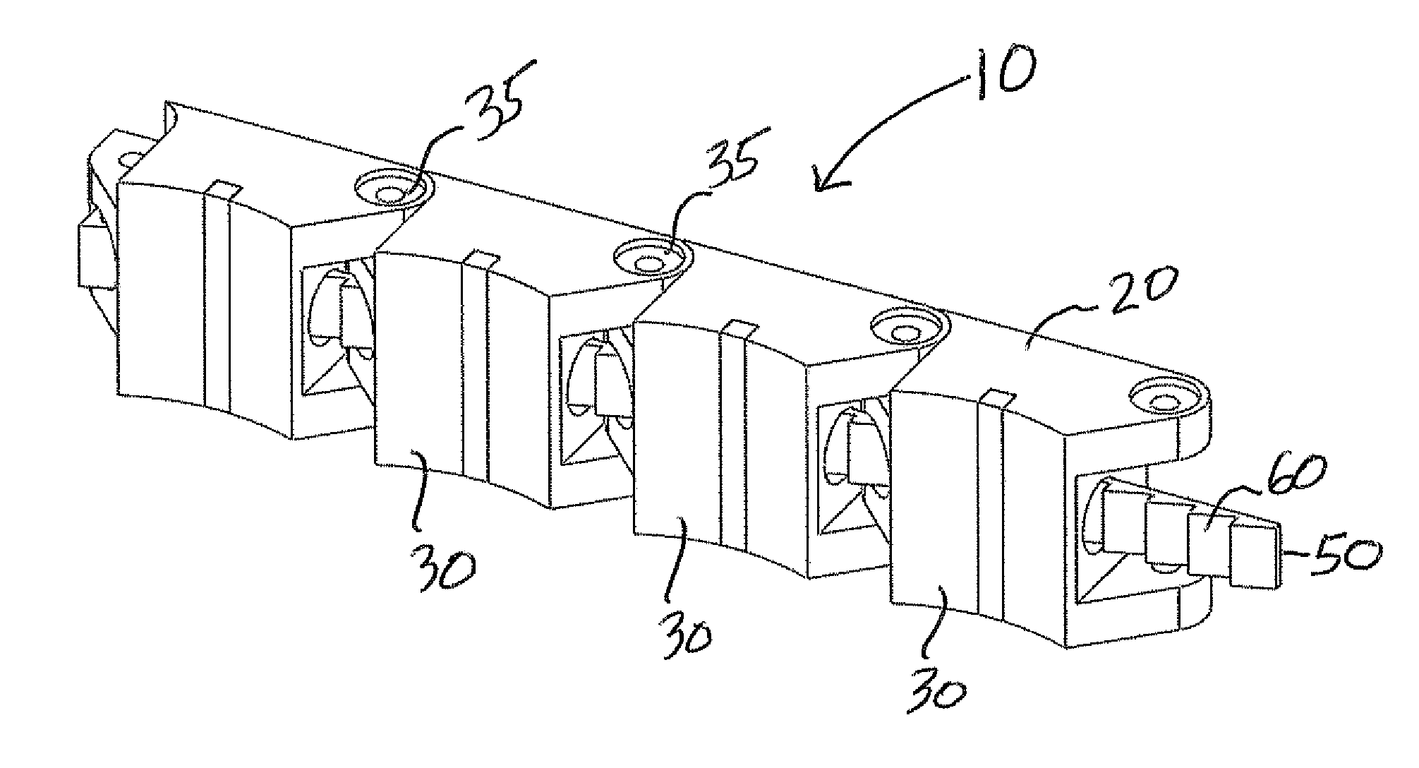
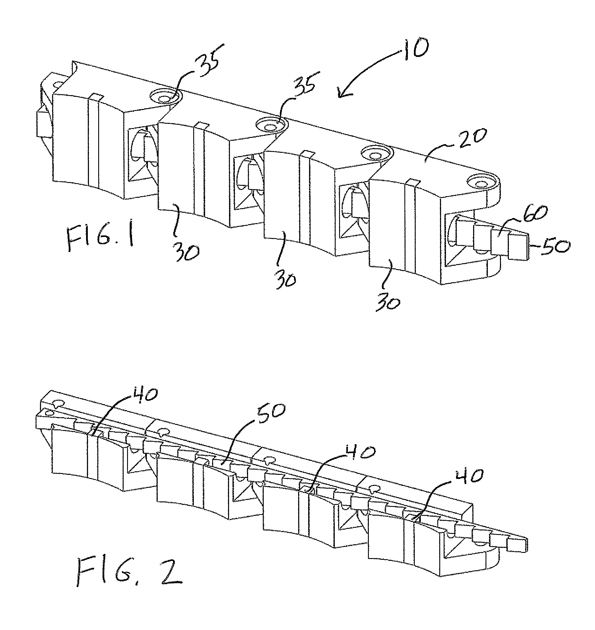
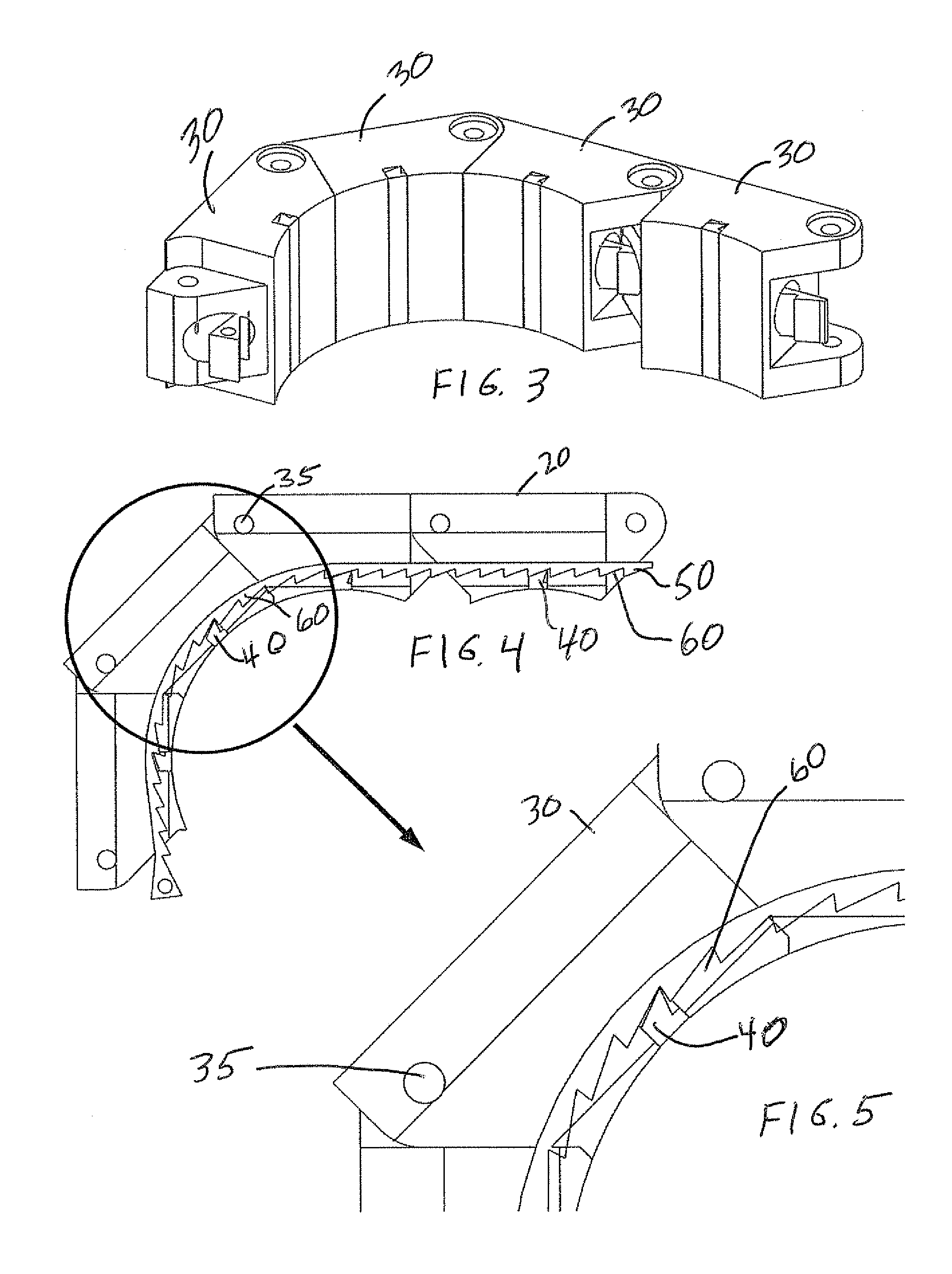
[0024]The present invention is an implant that may be used in the human body, for example during spinal surgery of various types. The implant may have a stable and secure locking arrangement. The present invention also includes a corresponding method for deploying the implant through a delivery conduit. The implant may include an implant body and a locking element. The locking arrangement may include projections on the locking element that may mate with engagement elements on the segments of the implant body along the flexing portion of the implant body. The projections may be bulges, teeth, elastic tabs, etc. The engagement elements may be steps, sockets, rectangular openings, etc. As each segment flexes, the projections fall into place in the engagement elements and the implant may be unable to open inside the body in which it has been placed.

[0025]In contrast to the prior art, in which the implant locking arrangement only involves locking one segment of the implant body, the impl...


PUM


Abstract

A medical device (10) includes an implant body (20) with a number of segments (30) hingedly interconnected so as to assume a straightened state for delivery and a flexed or roughly curved deployed state. Implant body may have engagement elements on at least two different segments, for example on a majority of segments. An elongated locking element anchored at the distal segment of the implant body may have projections for at least each engagement element. Tension applied to the locking element biases the implant body from the straightened state to the flexed deployed state. When the locking element is deflected to reach the curved deployed state, flexing segments of the implant body lock by matching engagement elements of the implant body with projections of the locking element. A very secure lock may be formed to prevent opening after deployment.

Description

FIELD AND BACKGROUND OF THE INVENTION[0001]The present invention claims priority to U.S. provisional patent application No. 61 / 304,857 filed 16 Feb. 2010 by Applicant Siegal.[0002]The present invention relates to implant bodies, such as for spinal surgery and, in particular, it concerns an implant device having a very stable locking arrangement to prevent the implant body from opening up once implanted into the body.[0003]Various devices have been proposed for implants and their deployment inside the spine or other parts of the body. An important feature of an implant is that it not only be delivered effectively but that it remain in position after deployment and not open in the body. Stability and a secure and reliable placement of the implant are critical. If the implant were to open after deployment, it could damage surrounding tissue and undo the effects of the spinal surgery.[0004]PCT patent application publication no. WO 2009 / 019669 of Applicant published 12 Feb. 2009 teaches ...

Claims


Application Information

Patent Timeline
IPC IPC(8): A61F2/44
CPCA61B17/7094A61F2220/0075A61F2/44A61F2/4455A61F2002/2835A61F2002/30331A61F2002/30367A61F2002/30462A61F2002/30469A61F2002/3052A61F2002/30522A61F2002/30624A61F2002/30632A61F2002/4415A61F2002/448A61F2002/4635A61F2220/0025A61F2220/0033A61B17/8852A61B17/70A61F2/28A61F2/02
Inventor SIEGAL, TZONYKEREN, DVIRLOEBL, ODEDTOUBIA, DIDIER
Owner SEASPINE
Why Eureka
Try Eureka