Eureka AIR delivers breakthrough ideas for toughest innovation challenges, trusted by R&D personnel around the world.

Rapid Emergency Evacuation Frame

a frame and emergency technology, applied in the field of emergency evacuation frames, can solve the problems of not providing any means to attach an intravenous stand, further injury to the patient, and the stretcher described herein does not address the need for a support, so as to achieve convenient transportation and improve fluid flow

Active Publication Date: 2013-02-14
DAVIS DAVID
View PDF11 Cites 6 Cited by
  • Summary
  • Abstract
  • Description
  • Claims
  • Application Information

AI Technical Summary

Benefits of technology

The present invention is an air liftable emergency evacuation frame that allows for secure transportation of an injured person to medical aid. The frame is lightweight, compact, and easy to transport. It includes a support structure with poles and a support member assembly. The frame is designed to hold a person in a secure and comfortable position and can also accommodate an intravenous bag for better fluid flow. It features a shoulder strap and leg strap for added security and a plurality of handles for easy transportation. The frame is ideal for carrying an injured person and can be easily accessed even in adverse weather conditions. It can be transported by one or two men and is ergonomically designed for all types of weather. Overall, the air liftable emergency evacuation frame provides a reliable and efficient means for transporting an injured person to medical aid.

Problems solved by technology

However, when the stretcher is in the transporting state, there is a chance for the mattress to bend and which would cause discomfort and further injury to the patient.
However, the stretcher described herein does not provide any means to attach an intravenous stand.
Nonetheless, the stretcher does not address the need for a support at the correct position for the rescuer to perform Cardiopulmonary Resuscitation (CPR) on the injured person.

Method used


Image

  • Rapid Emergency Evacuation Frame
  • Rapid Emergency Evacuation Frame
  • Rapid Emergency Evacuation Frame

Examples


Embodiment Construction

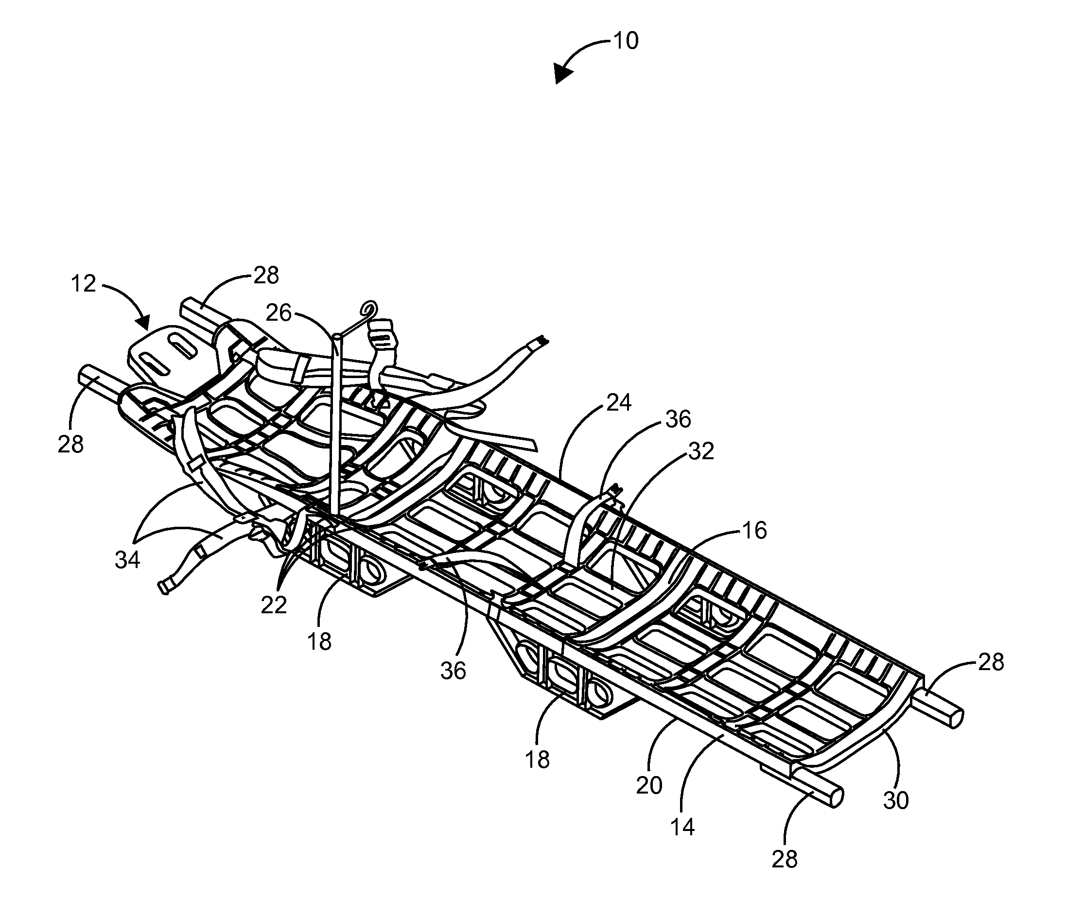
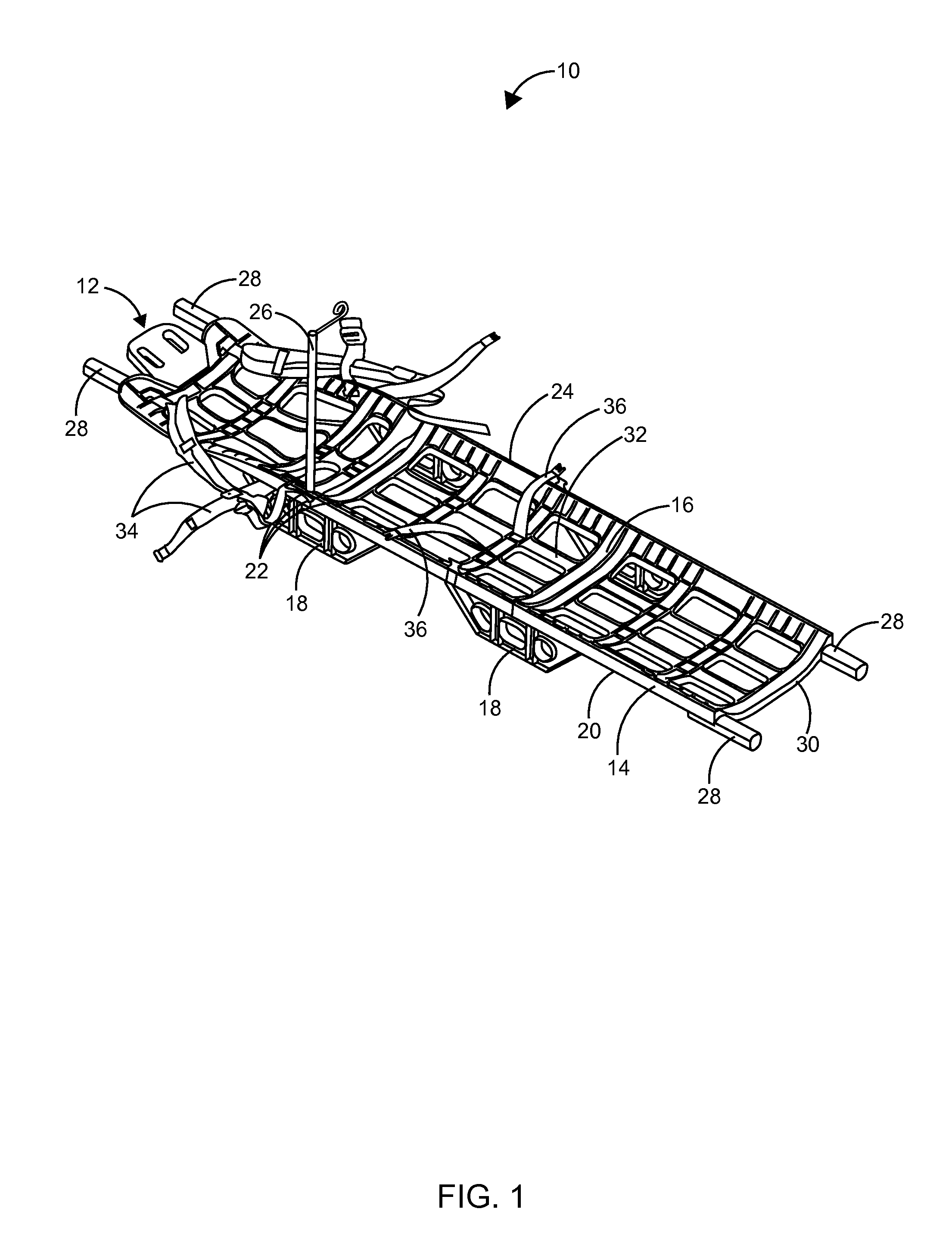
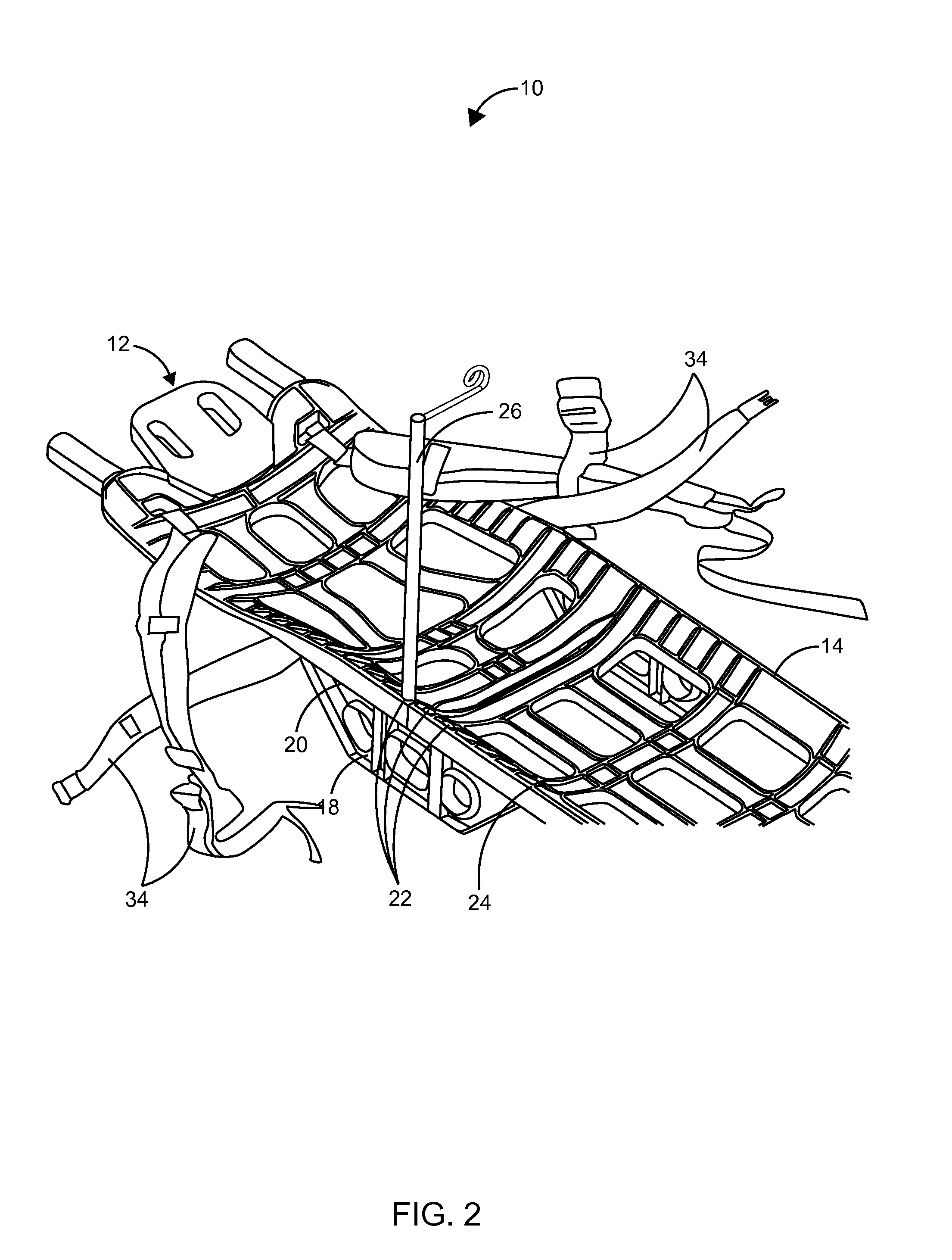
[0015]FIG. 1 shows a side perspective view of an air liftable emergency evacuation frame 10 for securely transporting an injured person to an immediate medical aid. The air liftable emergency evacuation frame 10 comprises an elongated support structure 12 that includes a longitudinally extending pair of opposing poles 14 and a support member assembly 16. The support member assembly 16 being configured to interconnect the pair of opposing poles 14. A plurality of supporting means 18 attached at a lower portion 20 of the pair of opposing poles 14 and at least one hole 22 is employed at an upper portion 24 of at least one of the pair of opposing poles 14 to hold an intravenous stand 26. A plurality of handles 28 are attached at a plurality of terminal ends 30 of the pair of opposing poles 14 to carry the injured person. The support member assembly 16 defines a recessed area 32 to place the injured person. The evacuation frame 10 includes a shoulder strap 34 and a leg strap 36 to secure...


PUM


Abstract

An air liftable emergency evacuation frame is for transporting an injured person to an immediate medical aid. The evacuation frame comprises an elongated support structure that includes a support member assembly having a longitudinally extending pair of opposing poles. The support member assembly is configured to interconnect the pair of opposing poles to define a recessed area to place the injured person. A plurality of supporting means attached at a lower portion of the pair of opposing poles is adaptable to hold the elongated support structure when the emergency evacuation frame is placed on a surface with the injured person. At least one hole is employed at an upper portion of at least one of the pair of opposing poles to hold a detachable intravenous stand. The detachable intravenous stand allows a rescuer to hang an intravenous bag for providing a better flow of fluids.

Description

CROSS-REFERENCE TO RELATED APPLICATIONS[0001]Not Applicable.STATEMENT REGARDING FEDERALLY SPONSORED RESEARCH AND DEVELOPMENT[0002]Not Applicable.FIELD OF THE INVENTION[0003]This invention relates to evacuation frames, and more particularly to an air liftable emergency evacuation frame for transporting an injured individual to an immediate medical aid.DISCUSSION OF RELATED ART[0004]A stretcher is a medical device used to carry an injured / immobile person from one place to another. The stretcher may be wheeled or carried by hand. Stretchers should be light weight, compact, efficient, strong, may be air liftable and should be easily accessible. Stretchers are intended for medical use in the military and for civilian use. Stretchers may contain straps for securely holding the body of the injured person. Stretchers must be washable and sanitary. Foldable stretchers are also available. Stretchers provide safety and the comfortable movement of patients and should reduce the risk of back inj...

Claims


Application Information

Patent Timeline
Patent Type & Authority Applications(United States)
IPC IPC(8): A61G1/00A61G1/04A61G1/044
CPCA61G1/044A61G1/00
Inventor DAVIS, DAVID
Owner DAVIS DAVID
Why Eureka
Eureka Blog
Learn More