Air flow measuring device

a technology of air flow and measuring device, which is applied in the direction of liquid/fluent solid measurement, instrumentation, structural/machine measurement, etc., can solve the problems of thermal insulation, resin material, and sensor precision may be reduced

Active Publication Date: 2013-02-14
DENSO CORP
View PDF6 Cites 62 Cited by
  • Summary
  • Abstract
  • Description
  • Claims
  • Application Information

AI Technical Summary

Problems solved by technology

Therefore, thermal insulation from, for example, a resin material, from which the sub-passage is made, is insufficient, and a precision of the sensor may be reduced due to a heat exchange with the resin material.
In addition, a flow of

Method used


Image

  • Air flow measuring device
  • Air flow measuring device
  • Air flow measuring device

Examples


Embodiment Construction

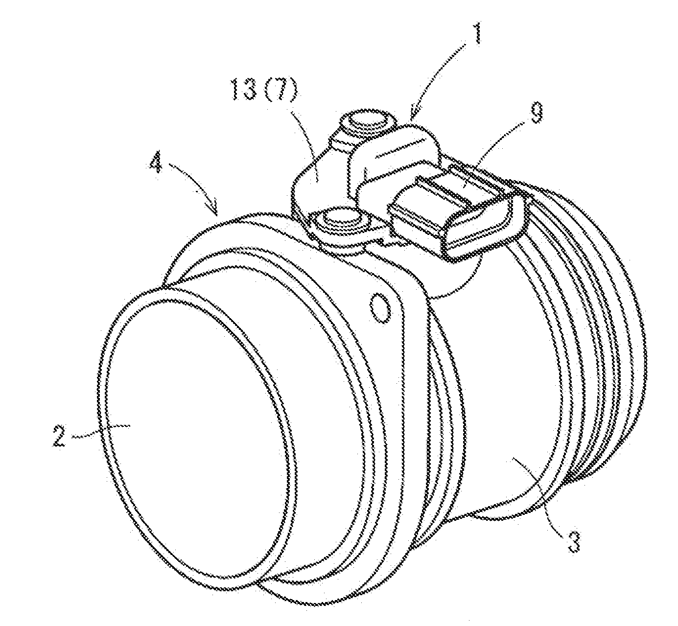
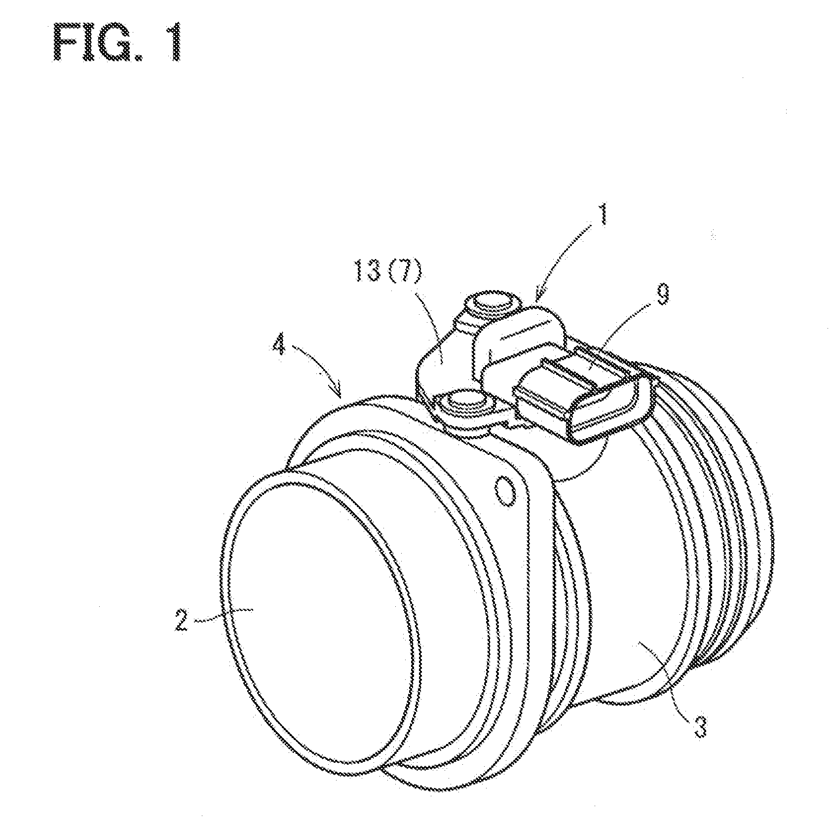
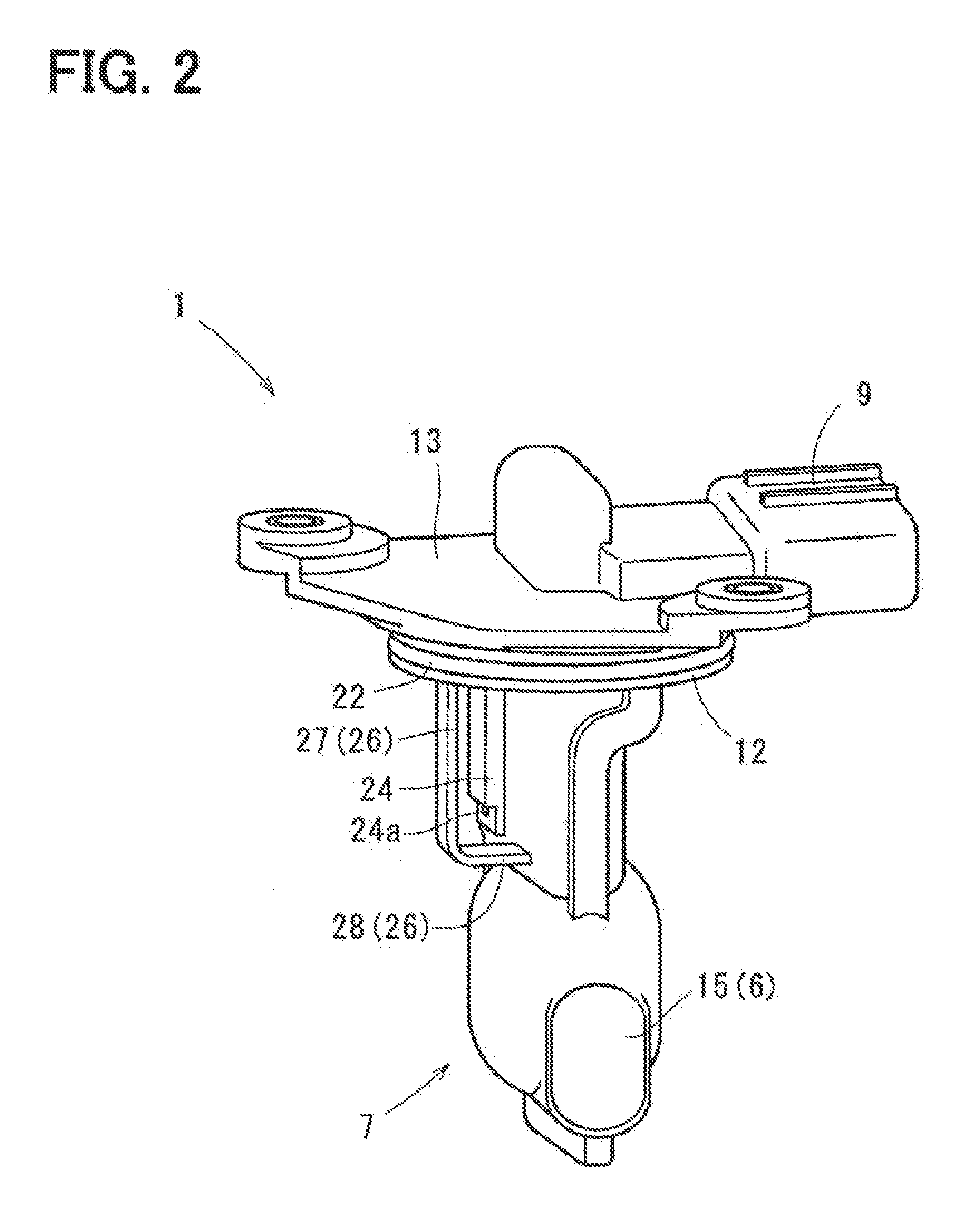
[0020]An air flow measuring device according to an embodiment is adapted to be disposed in an intake passage through which intake air drawn into an internal combustion engine flows, and is configured to measure a flow rate of intake air flowing through the intake passage. The device includes a housing, a flow sensor, and a humidity sensor. The housing defines a bypass flow passage through which intake air passes. A part of intake air is taken into the bypass flow passage to pass through the bypass flow passage. The flow sensor includes a sensing part disposed in the bypass flow passage, and is configured to produce a signal which is in accordance with the flow rate of intake air as a result of heat transfer between intake air taken into the bypass flow passage and the sensing part. The humidity sensor includes a sensing part exposed to the intake passage, and projects from an outer wall of the housing into the intake passage. The humidity sensor is configured to produce a signal whi...


PUM


Abstract

An air flow measuring device includes a housing, flow sensor, and a humidity sensor. The housing defines a bypass flow passage through which intake it passes. A part of intake air is taken into the bypass flow passage to pass through the bypass flow passage. The flow sensor includes a sensing part disposed in the bypass flow passage, and produces a signal which is in accordance with the flow rate of intake air as a result of heat transfer between intake air taken into the bypass flow passage and the sensing part. The humidity sensor includes a sensing part exposed to the intake passage, and projects from an outer wall of the housing into the intake passage. The humidity sensor produces a signal which is in accordance with humidity of intake ail flowing through the intake passage.

Description

CROSS REFERENCE TO RELATED APPLICATION[0001]This application is based on Japanese Patent Application No. 2011-173923 filed on Aug. 9, 2011, the disclosure of which is incorporated herein by reference.TECHNICAL FIELD[0002]The present disclosure relates to an air flow measuring device which measures a flow rate of air.BACKGROUND[0003]Conventional, a thermal-type air flow measuring device for measuring an air flow rate by use of heat transfer between the device and air is widely known. The air flow measuring device is disposed in an intake passage leading to an internal combustion engine to be used for measuring the flow rate of intake air suctioned into the engine (flow rate of intake air may be hereinafter referred to as an intake air amount).[0004]More specifically, this air flow measuring device takes in a part of intake air flowing through the intake passage and generates a signal in accordance with the intake air amount. The air flow measuring device includes a housing that defin...

Claims


Application Information

Patent Timeline
IPC IPC(8): G01M15/04
CPCG01F1/684G01F5/00G01F1/6842
Inventor KOHNO, YASUSHI
Owner DENSO CORP
Why Eureka
Try Eureka