
Sprinkler System and Installation

a technology of sprinkler system and installation, applied in the direction of thermal insulation, pipe protection, pipe protection by thermal insulation, etc., can solve the problem of unforgiving rigid design

Active Publication Date: 2013-02-14
VICTAULIC
View PDF9 Cites 13 Cited by
  • Summary
  • Abstract
  • Description
  • Claims
  • Application Information

AI Technical Summary

Benefits of technology

The invention is a sprinkler installation that includes a structure with a temperature-controlled interior and an exterior space separated by a substrate. A piping network is positioned in the controlled interior space and supplies fire-suppressing liquid. The installation includes at least one sprinkler assembly comprising a conduit extending through an opening in the substrate. The conduit has a valve that can be opened or closed to control the flow of liquid. A sprinkler is mounted on the end of the conduit and extends into the exterior space. The patent text describes how the sprinkler installation works and how it can help prevent fire outbreaks in buildings.

Problems solved by technology

It is a challenge to provide fire protection to such structures, especially when water is the preferred fire suppressing liquid because measures must be taken to ensure that the water does not freeze within the piping network or the sprinklers.
However, this rigid design is unforgiving with respect to the relative positioning of the openings and the dry sprinkler assemblies, requiring precise alignment between assembly and opening during construction and installation.

Method used


Image

  • Sprinkler System and Installation
  • Sprinkler System and Installation
  • Sprinkler System and Installation

Examples


embodiment 66

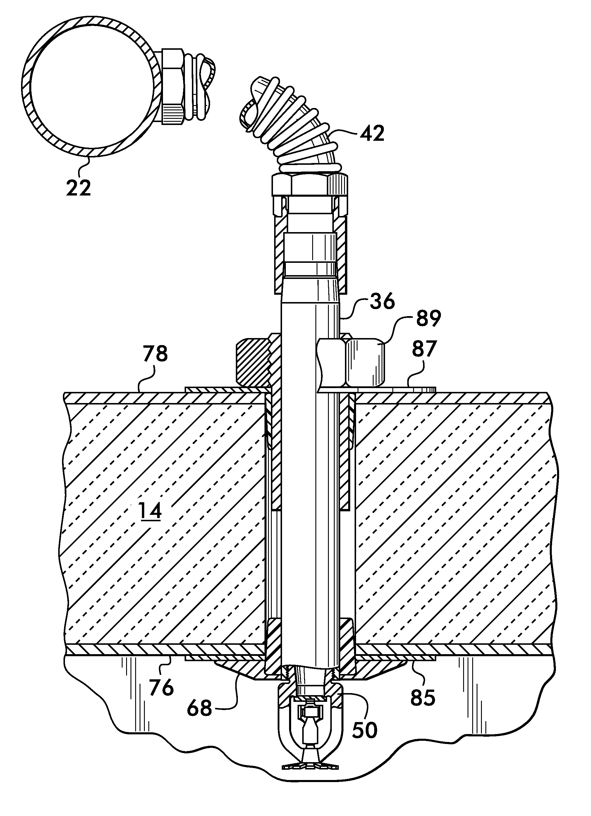
[0024]FIG. 4A shows another embodiment 66 of a sprinkler assembly according to the invention having a first sleeve 56a positioned proximate to the first end 38 of the conduit 36 and a second sleeve 56b positioned proximate to the second end 46 of the conduit. Again, the sleeves may be formed of insulating material such as natural rubber, EPDM, Buna N, PTFE, silicone, cork or other similar materials. As described above, each sleeve 56a and 56b may have an inwardly facing surface 58 which contacts the outwardly facing surface 60 of the conduit, and an outwardly facing surface 62 which contacts an inwardly facing surface 64 of the substrate 14 within the opening 44. Outwardly facing surfaces 62 of sleeves 56a and 56b may be tapered, and the sleeves cooperate to support the sprinkler assembly on the substrate.

[0025]Additional support for the sprinkler assembly 66 is provided by a pair of escutcheons 68 and 70 positioned surrounding the opening 44 on opposite sides of the substrate 14. I...

embodiment 82

[0026]Another sprinkler assembly embodiment 82 is illustrated in FIG. 5 wherein the escutcheon 70 is secured to the conduit 36 threadedly by compatible screw threads 84 and 86 respectively positioned on the escutcheon and the conduit. Rotation of the escutcheon 70 when in contact with the substrate surface 78 draws the escutcheon 68 into contact with the opposite surface 76 and thereby supports the sprinkler assembly 82 on the substrate and between the escutcheons. Note that the escutcheon 68 is shown in phantom line, which indicates that it may be attached to the assembly in one of a number of ways. For example, FIG. 6 shows escutcheon 68 attached to the conduit 36 by a clamp 88, whereas FIG. 7 shows the escutcheon 68 threadedly attached to the conduit 36 by means of compatible screw threads 90 and 92 respectively on the escutcheon and the conduit 36. Note that in the example embodiments shown in FIGS. 6 and 7 the second end 46 of the conduit extends from the opening 44 beyond the ...


PUM


Abstract

A sprinkler system installation for fire suppression within a cold environment uses a dry sprinkler assembly connected to a piping network by a flexible hose and supported in a substrate of a structure separating the cold environment from a temperature controlled warm environment. Sleeves of insulating material surround a conduit of the assembly and engage both the conduit and the substrate to seal and provide support. Escutcheons are also provided on opposite sides of the substrate which effect a clamping action on the assembly.

Description

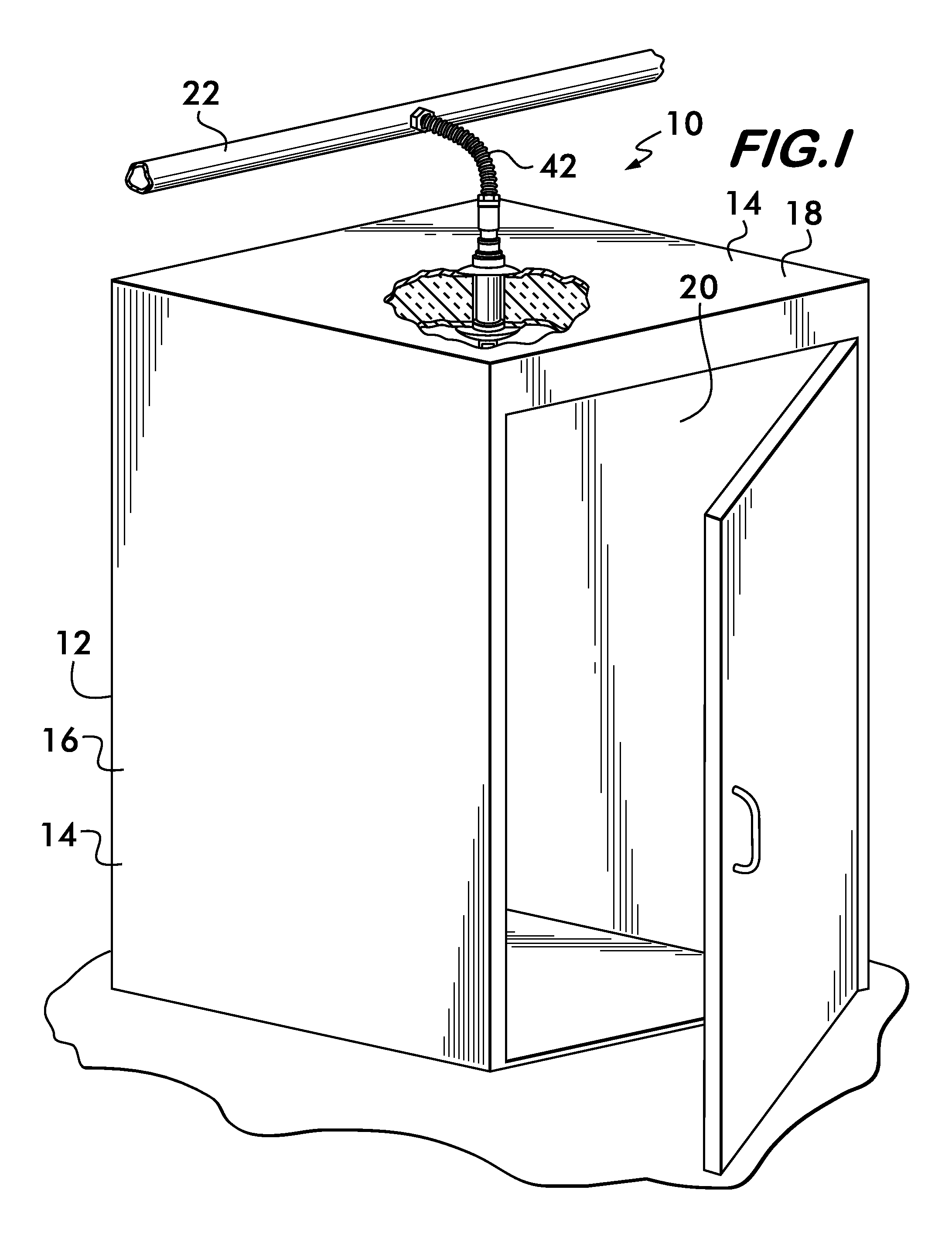
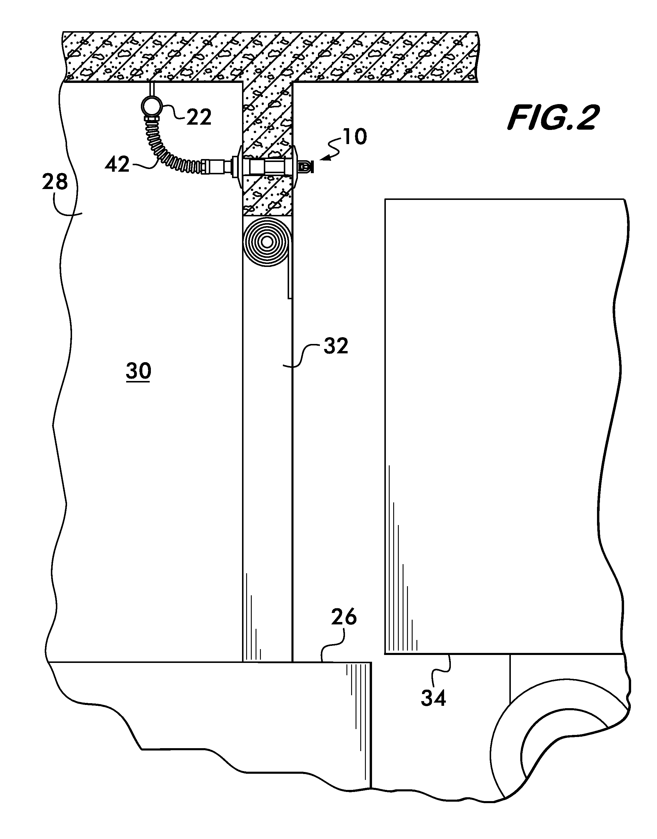
FIELD OF THE INVENTION[0001]This invention concerns sprinkler systems and installations at the interface between environments having large temperature differences.BACKGROUND[0002]Sprinkler systems for fire suppression are used to protect structures which separate or enclose adjacent regions having large temperature differences from one another. Examples of such structures include freezers, balconies of apartments, and loading docks of warehouses. Each of these structures has one or more walls and / or ceilings, which separate a region wherein the temperature is maintained above the freezing point of water from a region where the temperature is maintained below freezing or can drop below freezing.[0003]It is a challenge to provide fire protection to such structures, especially when water is the preferred fire suppressing liquid because measures must be taken to ensure that the water does not freeze within the piping network or the sprinklers. To meet this challenge it is known to posit...

Claims


Application Information

Patent Timeline
Patent Type & Authority Applications(United States)
IPC IPC(8): A62C35/00A62C3/00
CPCA62C37/11A62C35/68F16L59/121A62C35/62A62C3/004A62C37/08
Inventor SZENTIMREY, RUDOLFSTEMPO, JOHN M.MCWHIRTER, ERIC
Owner VICTAULIC
Learn More