Insulated wire
Active Publication Date: 2013-02-14
ESSEX FURUKAWA MAGNET WIRE JAPAN CO LTD +1
View PDF0 Cites 62 Cited by
- Summary
- Abstract
- Description
- Claims
- Application Information
AI Technical Summary
Benefits of technology
The present invention is about an insulated wire that has a conductor and a baked enamel layer containing a polyamide-imide on its outer periphery. The wire also has an extrusion-coated resin layer on the outer side of the baked enamel layer. The baked enamel layer has functional groups like carboxyl, ester, ether, and hydroxyl on its outer surface, which adhere to the extrusion-coated resin layer. The technical effect of this invention is better insulation and protection of the conductor, resulting in safer and reliable electrical performance.
Problems solved by technology
Accordingly, even if a connection cable is short, the surge voltage is high, and voltage decay due to the connection cable is also low.
However, these techniques were not so satisfactory in terms of the constitution of the thickness of the enamel layer or the extruded coating, from the standpoint of balancing between the partial discharge-occurring voltage and the adhesiveness between the conductor and the enamel layer.
Method used
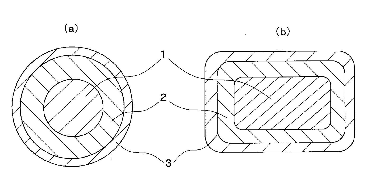
View moreImage
Smart ImageViewing Examples
Examples
examples
[0062]The present invention is described in more detail based on examples given below, but the present invention is not limited by the following examples.
Login to View More PUM
| Property | Measurement | Unit |
|---|---|---|
| Shape | aaaaa | aaaaa |
| Melting point | aaaaa | aaaaa |
| Heat capacity | aaaaa | aaaaa |
Abstract
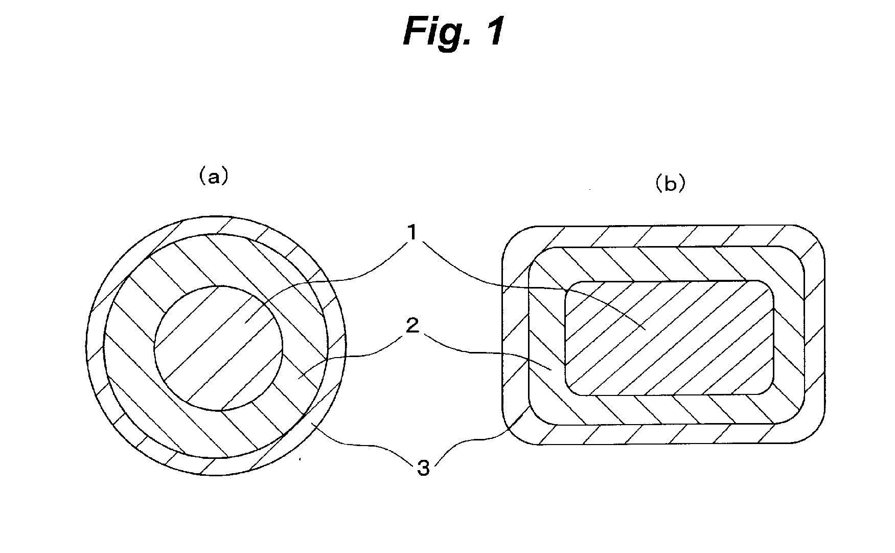
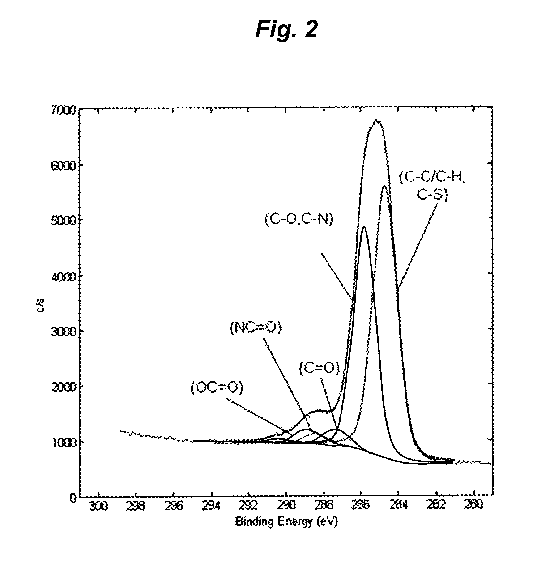
An insulated wire having:a conductor,a baked enamel layer containing at least a polyamide-imide provided on the outer periphery of the conductor directly or through an insulated layer, andat least one extrusion-coated resin layer provided on the outer side of the baked enamel layer,wherein the baked enamel layer has at least one functional group selected from the group consisting of a carboxyl group, an ester group, an ether group and a hydroxyl group on the outer surface thereof, and adheres to the extrusion-coated resin layer.
Description
FIELD OF THE INVENTION[0001]The present invention relates to an insulated wire.BACKGROUND OF THE INVENTION[0002]Inverters have been employed in many types of electrical equipments, as an efficient variable-speed control unit. Inverters are switched at a frequency of several kHz to tens of kHz, to cause a surge voltage at every pulse thereof. Inverter surge is a phenomenon in which reflection occurs at a breakpoint of impedance, for example, at a starting end, a termination end, or the like of a connected wire in the propagation system, followed by applying a voltage twice as high as the inverter output voltage at the maximum. In particular, an output pulse occurred due to a high-speed switching device, such as an IGBT (Insulated Gate Bipolar Transistor), is high in steep voltage rise. Accordingly, even if a connection cable is short, the surge voltage is high, and voltage decay due to the connection cable is also low. As a result, a voltage almost twice as high as the inverter outpu...
Claims
Login to View More Application Information
Patent Timeline
 IPC IPC(8): H01B3/30H01B7/00
CPCH01B7/0216H01B3/30H01B3/306
Inventor IKEDA, KEISUKEOYA, MAKOTOKANO, YOSHIHISAAOKI, TAKASHIMAKISHIMA, TATSUNORISUGIURA, AKIOASAI, HIROMITSUMATSUBARA, SHINICHI
Owner ESSEX FURUKAWA MAGNET WIRE JAPAN CO LTD
Features
- R&D
- Intellectual Property
- Life Sciences
- Materials
- Tech Scout
- Unparalleled Data Quality
- Higher Quality Content
- 60% Fewer Hallucinations
Learn More Browse by: Latest US Patents, China's latest patents, Technical Efficacy Thesaurus, Application Domain, Technology Topic, Popular Technical Reports.
© 2025 PatSnap. All rights reserved.Legal|Privacy policy|Modern Slavery Act Transparency Statement|Sitemap|About US| Contact US: help@patsnap.com


