Inductively charged vehicle with automatic positioning

a technology of inductive charging and automatic positioning, which is applied in the field of vehicles, can solve the problems of no device, difficulty in viewing the coil mounted on the vehicle on the display unit via the camera provided on the side face of the vehicle, and inability to mount a camera on the vehicle, so as to facilitate the alignment of an electric power transmitting coil and an electric power receiving coil

Active Publication Date: 2013-02-14
TOYOTA JIDOSHA KK
View PDF12 Cites 70 Cited by
  • Summary
  • Abstract
  • Description
  • Claims
  • Application Information

AI Technical Summary

Benefits of technology

[0016]The invention provides a vehicle, in which an electric power receiving coil that receives electric power from an electric power transmitting coil provided externally to the vehicle is disposed at the bottom of the vehicle, and which vehicle facilitates the alignment of the electric power transmitting coil and the electric power receiving coil.
[0020]According to the vehicle of the invention, the alignment of an electric power transmitting coil and an electric power receiving coil is facilitated.

Problems solved by technology

When the coil mounted on the vehicle is disposed at the bottom of the vehicle, however, it is difficult to view the coil mounted on the vehicle on the display unit via the camera that is provided on a side face of the vehicle.
Thus, mounting a camera on a vehicle does not necessarily facilitate the alignment of the coil mounted on the vehicle and the coil on the charging facility side.
Note that the above conventional vehicle parking system or the like has no device that facilitates the alignment of the coil mounted on the vehicle and the coil on the charging facility side when the coil mounted on the vehicle is disposed at the bottom of the vehicle.

Method used


Image

  • Inductively charged vehicle with automatic positioning
  • Inductively charged vehicle with automatic positioning
  • Inductively charged vehicle with automatic positioning

Examples


Embodiment Construction

[0046]Embodiments of the invention will be described in detail below with reference to the drawings. Note that the same or corresponding portions in the drawings are designated by the same reference numeral and the description thereof is not repeated.

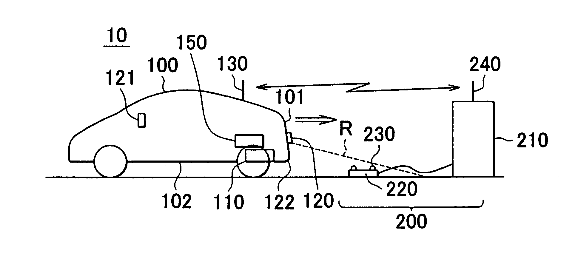
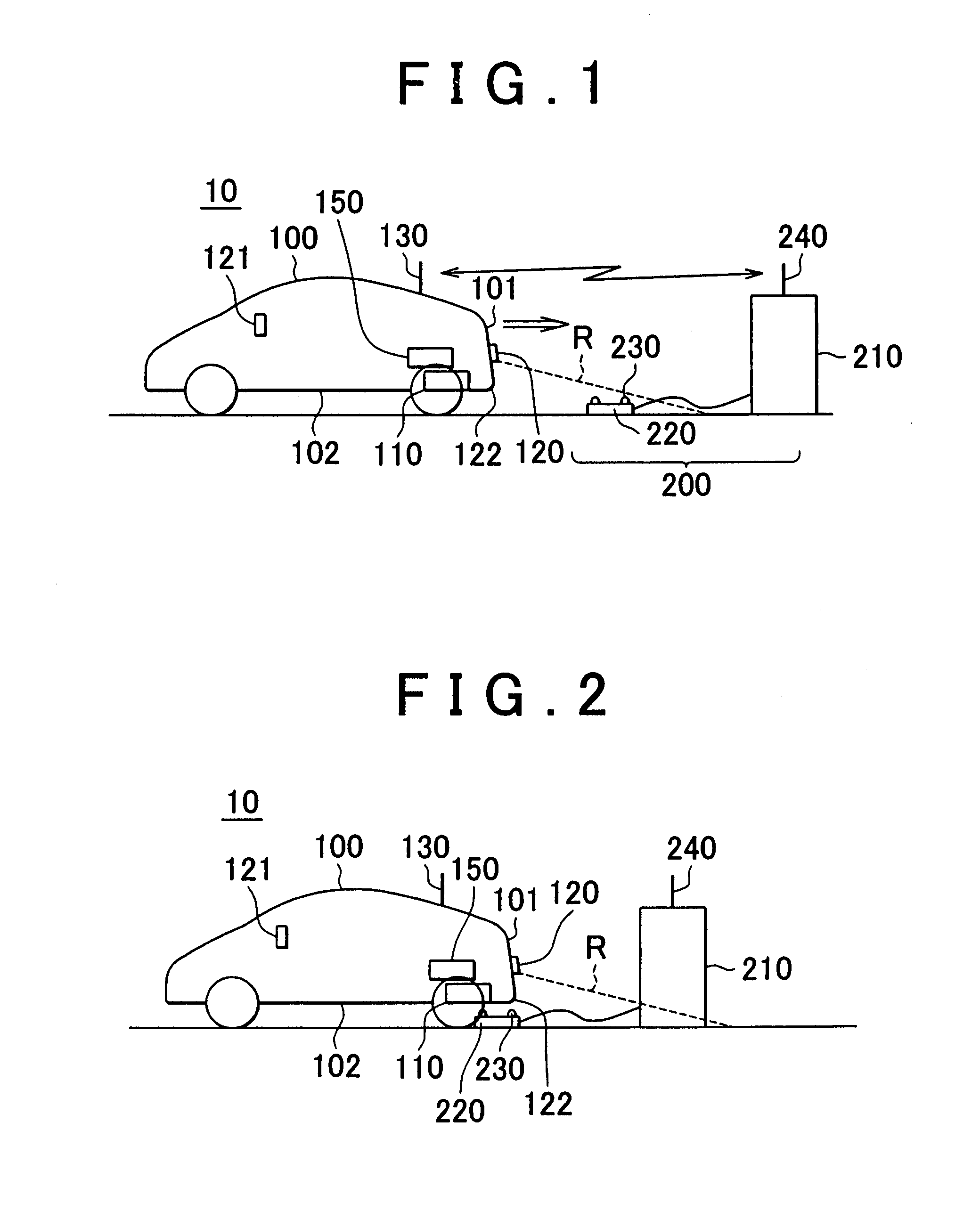
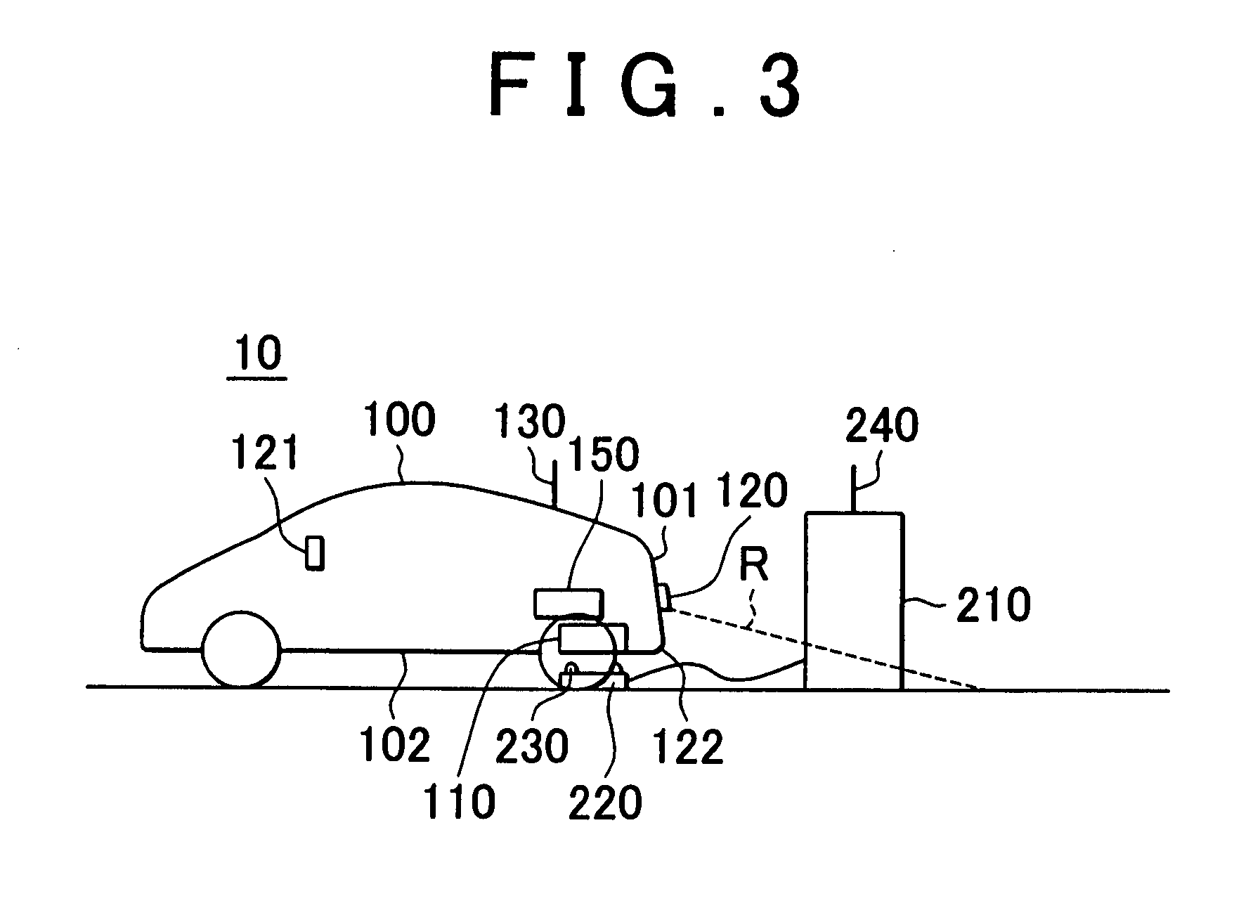
[0047]FIG. 1 is an overall configuration diagram of a vehicle power supply system according to the embodiment of the invention. Referring to FIG. 1, the vehicle power supply system 10 includes an electric vehicle 100 and a power supply facility 200. The electric vehicle 100 includes an electric power receiving unit 110, a camera 120, and a communication unit 130.

[0048]The electric power receiving unit 110 is fixed at the bottom of a vehicle body and is configured to receive, in a non-contact manner, electric power sent from an electric power transmitting unit 220 of the power supply facility 200. The electric power receiving unit 110 includes a secondary self-resonant coil and receives, in a non-contact manner, electric power from the e...


PUM


Abstract

An electric vehicle receives electric power, in a non-contact manner, from an electric power transmitting coil provided externally to the vehicle. The electric vehicle includes an electric power receiving unit that is disposed at a bottom of the vehicle and receives electric power from the electric power transmitting unit via electromagnetic field resonance; a camera that captures an image of the outside; and a display unit that displays an outside view from the vehicle that is captured by the camera. The electric power receiving unit is disposed at a position that is offset toward a peripheral face, on which the camera is disposed, with respect to the center of the bottom in the longitudinal direction of the vehicle.

Description

BACKGROUND OF THE INVENTION[0001]1. Field of the Invention[0002]The invention relates to a vehicle and in particular to a vehicle that receives electric power, in a non-contact manner, from an electric power transmitting coil provided externally to the vehicle.[0003]2. Description of the Related Art[0004]Various charging systems, such as a charging system that wirelessly charges a battery mounted on a vehicle, have been proposed.[0005]In Japanese Patent Application Publication No. 2004-229425 (JP-A-2004-229425), a vehicle parking system is described that charges a battery mounted on a vehicle with the use of radio waves, such as microwaves.[0006]In this vehicle parking system, an energy supply facility installed at a parking lot, or car park, or an energy station, transmits microwaves to the vehicle while the vehicle is parked. A microwave generator generates microwaves that are higher in intensity than the microwaves that is supplied to the vehicle while the vehicle is running. The...

Claims


Application Information

Patent Timeline
Patent Type & Authority Applications(United States)
IPC IPC(8): B60L9/16B60K1/04B60K13/04B60L5/00B60L50/15B60L50/16B60M7/00B60R1/00H02J7/00
CPCB60L11/123Y02T10/7275B60L11/182B60L11/1831B60L11/1833B60L11/1835B60L2210/14B60L2210/40B60L2220/14Y02T10/7005Y02T10/7088Y02T90/12Y02T90/122Y02T90/125Y02T90/14Y02T10/7077Y02T10/7241Y02T10/7225Y02T90/127Y02T10/6217Y02T90/121B60L11/14Y02T10/7072B60L50/61B60L50/16B60L53/38B60L53/39B60L53/36B60L53/37B60L53/126Y02T10/62Y02T10/72Y02T10/70
Inventor ICHIKAWA, SHINJI
Owner TOYOTA JIDOSHA KK
Why Eureka
Try Eureka