Secondary coil structure of inductive charging system for electric vehicles

a charging system and secondary coil technology, applied in the direction of electric vehicle charging technology, charging stations, transportation and packaging, etc., can solve the problems of unsuitable secondary coils mounted on vehicles for inductive charging, and the coils are rather bulky for certain installations, so as to reduce the heat generated in the vehicle body

Inactive Publication Date: 2013-02-14
PLUGLESS POWER INC
View PDF10 Cites 39 Cited by
  • Summary
  • Abstract
  • Description
  • Claims
  • Application Information

AI Technical Summary

Benefits of technology

[0007]The coil generates a magnetic field when current flows through the coil. The field created by the planar coil construction in the area of the vehicle body has a lower maximum value than that created by a conventional construction, thereby reducing heat generated in the vehicle body.

Problems solved by technology

The coil has both a lateral thickness and a vertical height which makes the coil rather bulky for certain installations such as when mounted on a vehicle for inductive charging.
While these prior coil constructions operate satisfactorily, they have inherent drawbacks which make them unsuitable for use as a secondary coil mounted on a vehicle for inductive charging.

Method used


Image

  • Secondary coil structure of inductive charging system for electric vehicles
  • Secondary coil structure of inductive charging system for electric vehicles
  • Secondary coil structure of inductive charging system for electric vehicles

Examples


Embodiment Construction

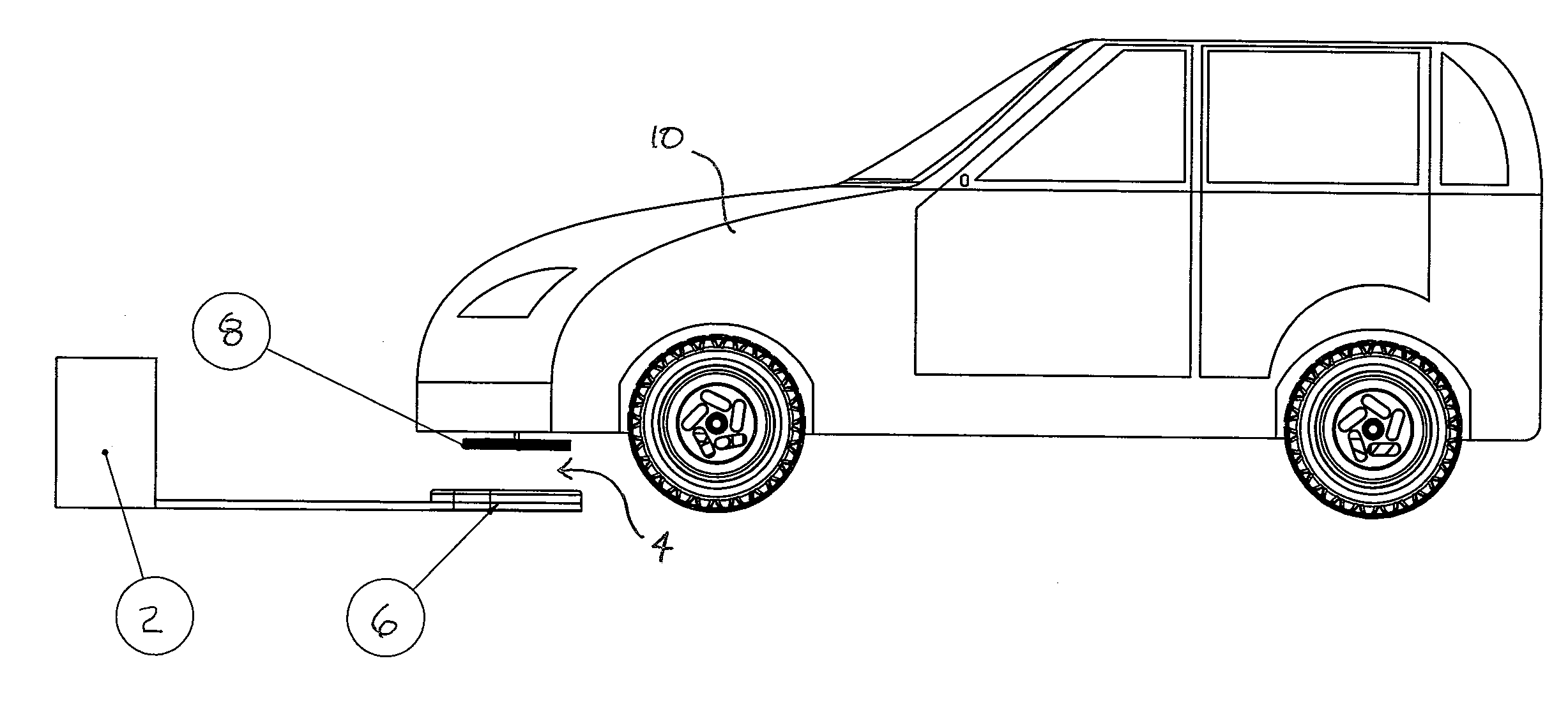
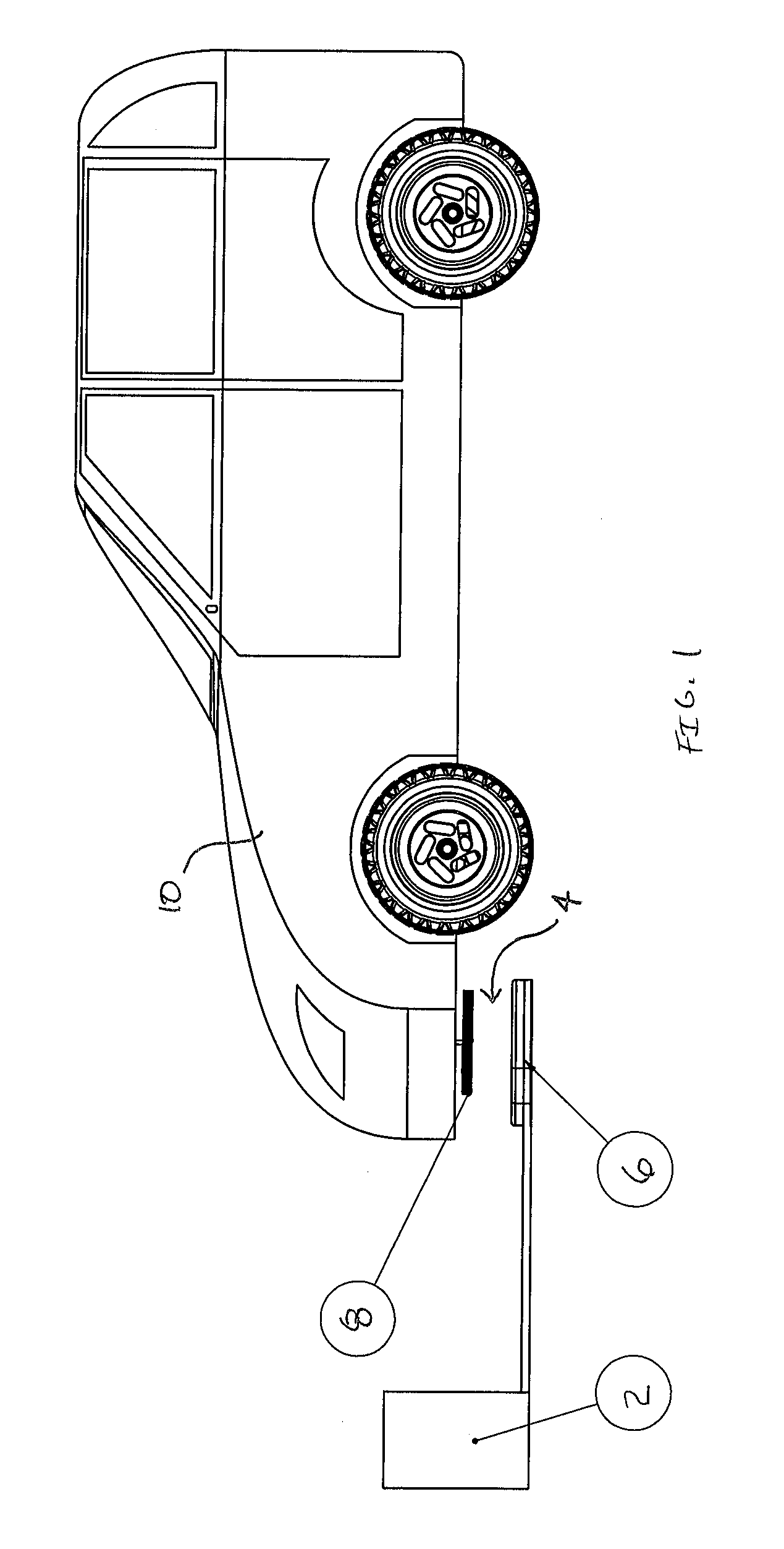
[0025]Referring first to FIG. 1, there is shown an inductive charging system for electric vehicles. The system includes a charging station 2 and a transformer 4. The transformer includes a stationary primary coil 6 which is preferably mounted on the ground such as the floor of a garage. The primary coil is connected with the charging station. The transformer further includes a secondary coil 8 which is mounted on a vehicle 10. The secondary coil is mounted at a location on the vehicle so that the vehicle can be positioned adjacent to the charging station with the secondary coil above the primary coil as shown. Preferably, the coils are arranged with their axes in alignment for maximum energy transfer there between. The charging station 2 is connected with a power source 12.

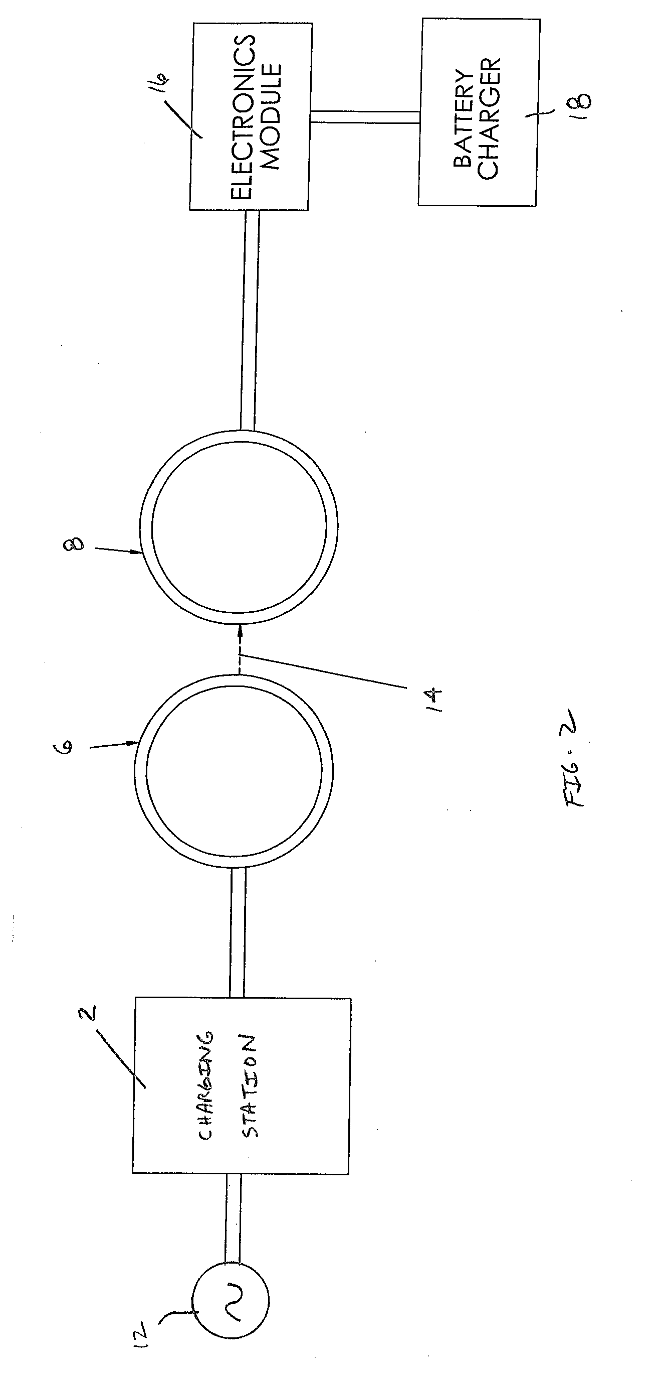
[0026]The inductive charging system according to the invention will be described in greater detail with reference to FIG. 2. The charging station 2 is connected with a power source 12. The power source is preferab...


PUM


Abstract

A secondary coil structure for an electric vehicle charging system is characterized by a flexible sheet of synthetic plastic material which acts as a substrate for a coil connected with the top surface of the sheet. The coil has an axis generally normal to the sheet. A second sheet of material is connected with the first sheet with the coil arranged between the sheets. The secondary coil may be configured to match the configuration of a component of the vehicle with which the secondary coil is connected. When electric current is introduces into the coil, the coil generates an elongated magnetic field with a lower maximum value in the vicinity of the vehicle components than that created by a conventionally wound coil, thereby minimizing heat generated in steel components of the vehicle body.

Description

BACKGROUND OF THE INVENTION[0001]Electric vehicle energy storage systems are normally recharged using direct contact conductors between an alternating current (AC) source such as is found in most homes in the form of electrical outlets; nominally 120 or 240 VAC or using inductive battery charging devices. Inductive charging devices utilize a transformer having primary and secondary windings to charge the battery of the vehicle. The primary winding is mounted in a stationary charging unit where the vehicle is stored and the secondary winding is mounted on the vehicle.[0002]To maximize efficiency, it is important that the secondary winding on the vehicle be aligned with and in close proximity to the primary winding in the stationary charging unit. This requirement presents some difficulties in the structure of the secondary coil. If the coil extends too far below the vehicle, it can be damaged by striking road objects when the vehicle is in operation. On the other hand, if the seconda...

Claims


Application Information

Patent Timeline
Patent Type & Authority Applications(United States)
IPC IPC(8): H02J7/00
CPCH02J5/005H02J7/025Y02T90/122Y02T10/7005Y02T90/14B60L11/182Y02T10/7072B60L53/126Y02T10/70H02J50/10H02J50/12Y02T90/12
Inventor RAEDY, STEVEN
Owner PLUGLESS POWER INC
Why Eureka
Try Eureka