Method and Apparatus for Controlling LCL Converters Using Asymmetric Voltage Cancellation Techniques

a technology of asymmetric voltage cancellation and lcl converter, which is applied in the field of methods, can solve the problems of conversion loss in transmitter electronics, and achieve the effects of improving efficiency, poor turn off characteristics, and huge diode reverse recovery loss

Inactive Publication Date: 2013-02-14
UTAH STATE UNIVERSITY
View PDF0 Cites 40 Cited by
  • Summary
  • Abstract
  • Description
  • Claims
  • Application Information

AI Technical Summary

Benefits of technology

The patent describes an improved method for controlling MOSFET devices in power electronics that can reduce loss caused by the device's own properties. By canceling out voltage asymmetries during operation, this approach helps achieve better results when transferring power through inductors. Additionally, faster switching times and lower resistivity levels make it possible to use these devices more efficiently in IPT systems. Overall, this innovation allows for greater efficiency and reduced energy waste in power conversion applications.

Problems solved by technology

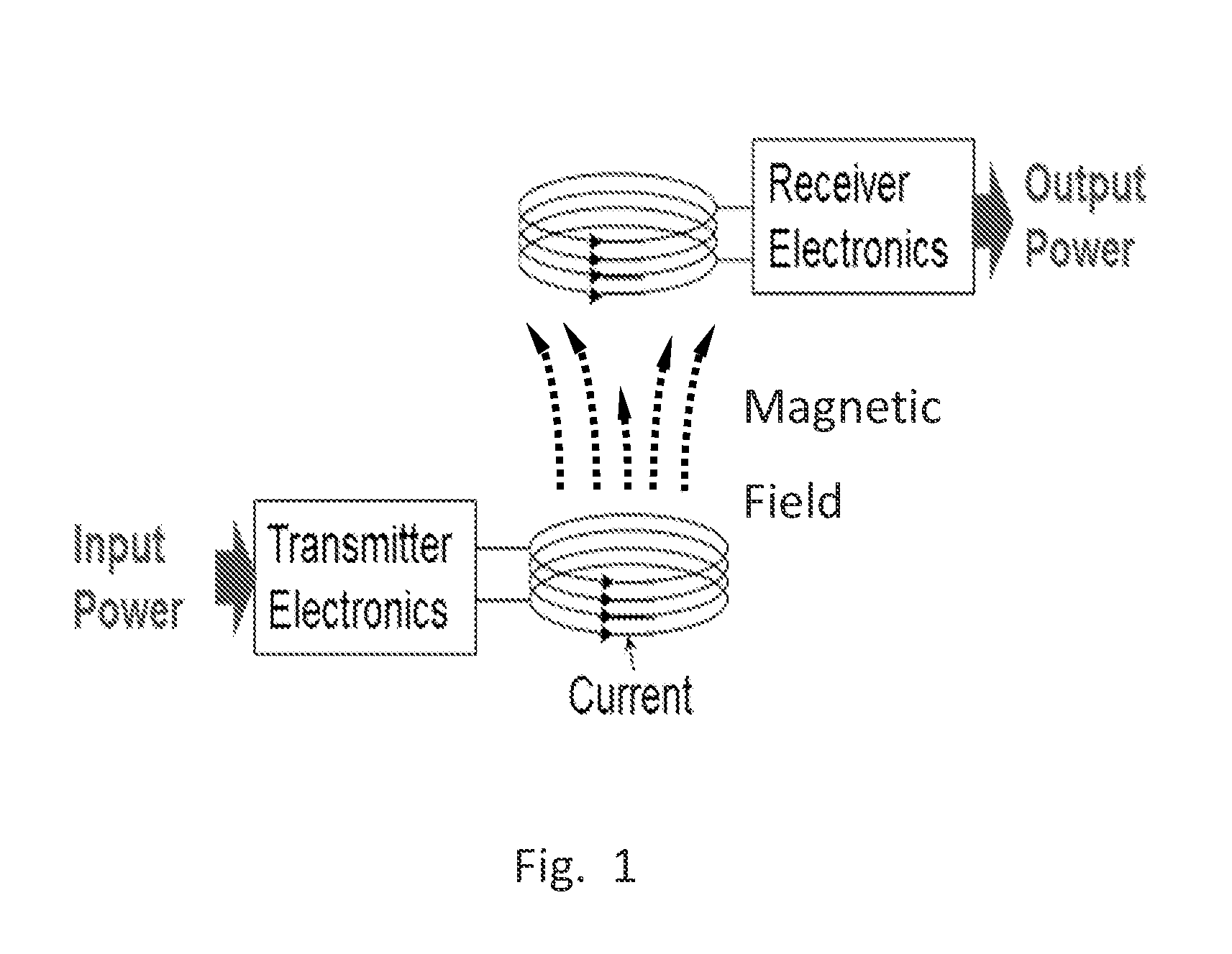
The patent text discusses a method of wireless power transfer called Inductive Power Transfer (IPT). This method uses electrical energy to create magnetic fields that can be transformed into electricity to power a load. The technical problem being addressed is how to create a system that can continuously charge electric vehicles without needing a physical connection between the vehicle and the roadway.

Method used


Image

  • Method and Apparatus for Controlling LCL Converters Using Asymmetric Voltage Cancellation Techniques
  • Method and Apparatus for Controlling LCL Converters Using Asymmetric Voltage Cancellation Techniques
  • Method and Apparatus for Controlling LCL Converters Using Asymmetric Voltage Cancellation Techniques

Examples


examples

[0121]It will be appreciated that various of the above-disclosed and other features and functions, or alternatives thereof, may be desirably combined into many other different systems or applications. Also, various presently unforeseen or unanticipated alternatives, modifications, variations or improvements therein may be subsequently made by those skilled in the art, and are also intended to be encompassed by the following claims.

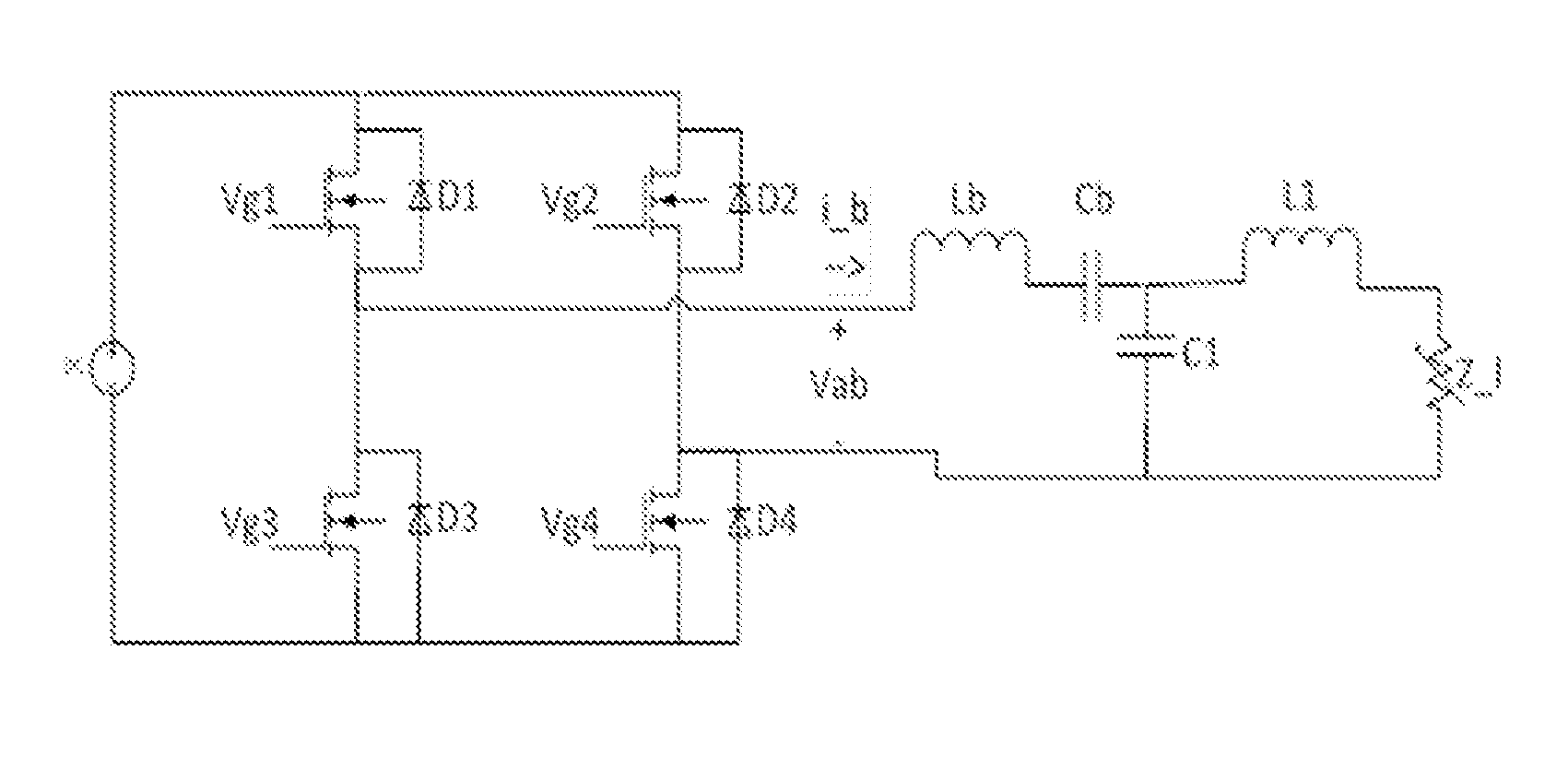
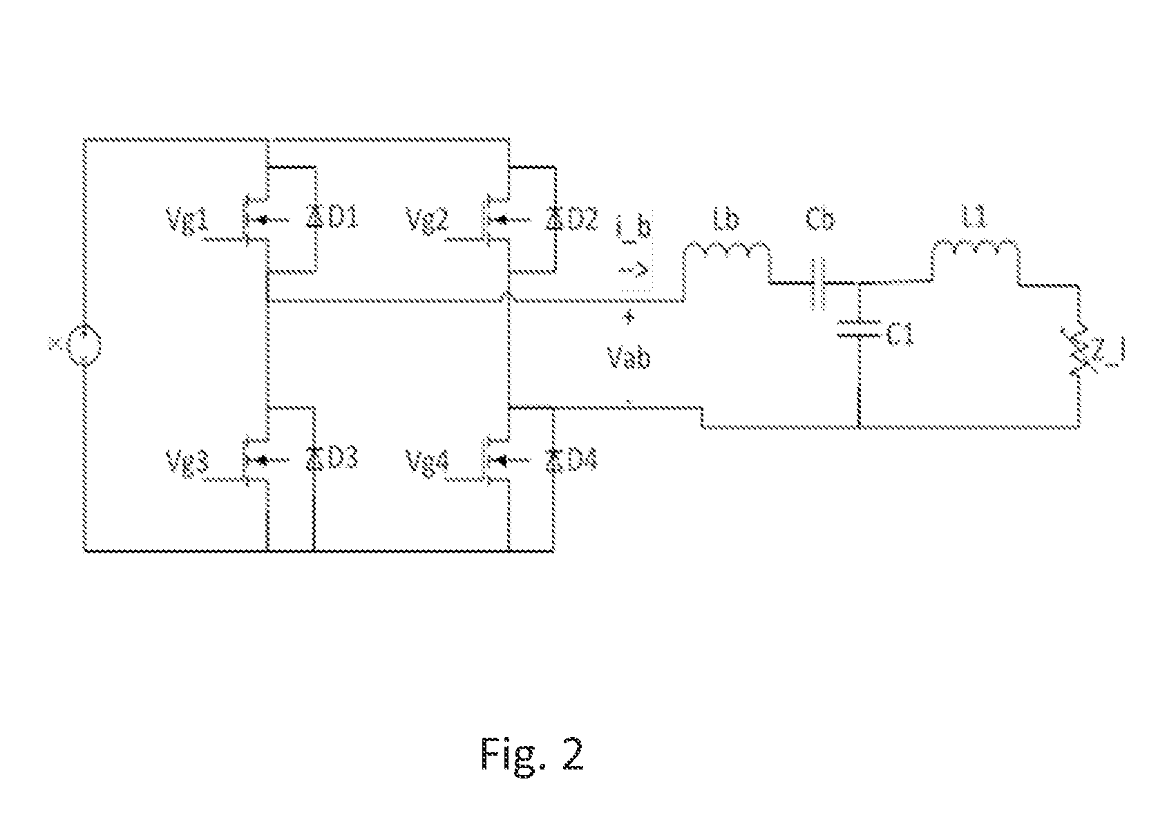
[0122]An overall design configuration of one embodiment of the apparatus, which has the parameter values shown in FIG. 36, is illustrated in FIG. 37. FIG. 38 is a schematic of the gate drivers. FIG. 39 illustrates a current path through the disclosed system.

[0123]FIG. 40 shows a high level block diagram of one embodiment of the system. The dotted blue line denotes isolation, as the NanoBoard 3000 controller communicates with the rest of the circuit via opto-isolators. FIG. 41 shows a resonant tank of the LCL converter.

[0124]In this embodiment, software pro...


PUM


Abstract

A method and apparatus for LCL resonant converter control utilizing Asymmetric Voltage Cancellation is described. The methods to determine the optimal trajectory of the control variables are discussed. Practical implementations of sensing load parameters are included. Simple PI, PID and fuzzy logic controllers are included with AVC for achieving good transient response characteristics with output current regulation.

Description


Claims


Application Information

Patent Timeline
Owner UTAH STATE UNIVERSITY
Why Eureka
Try Eureka