Method and device for generating voltage peaks in an electrostatic precipitator

a precipitator and voltage peaks technology, applied in the direction of ac-dc conversion, electric variable regulation, electric supply techniques, etc., can solve the problems of low degree of cleaning, relatively high resistance of dust, and low voltage sub-pulse,

Inactive Publication Date: 2002-04-16
KRAFTELEKTRONIK
View PDF7 Cites 63 Cited by
  • Summary
  • Abstract
  • Description
  • Claims
  • Application Information

AI Technical Summary

Problems solved by technology

The first category generates rectified voltage pulses of which the growth derivative is in step with that of the mains voltage, which results in a relatively inexpensive arrangement which, however, on account of a low growth derivative, has a relatively low degree of cleaning, particularly for dust with high resistivity.
These arrangements achieve a high degree of dust separation for dust with high resistivity as well, but are relatively expensive.
A drawback of this method is that each voltage sub-pulse corresponds on a one-to-one basis to a current pulse.

Method used


Image

  • Method and device for generating voltage peaks in an electrostatic precipitator
  • Method and device for generating voltage peaks in an electrostatic precipitator
  • Method and device for generating voltage peaks in an electrostatic precipitator

Examples


Embodiment Construction

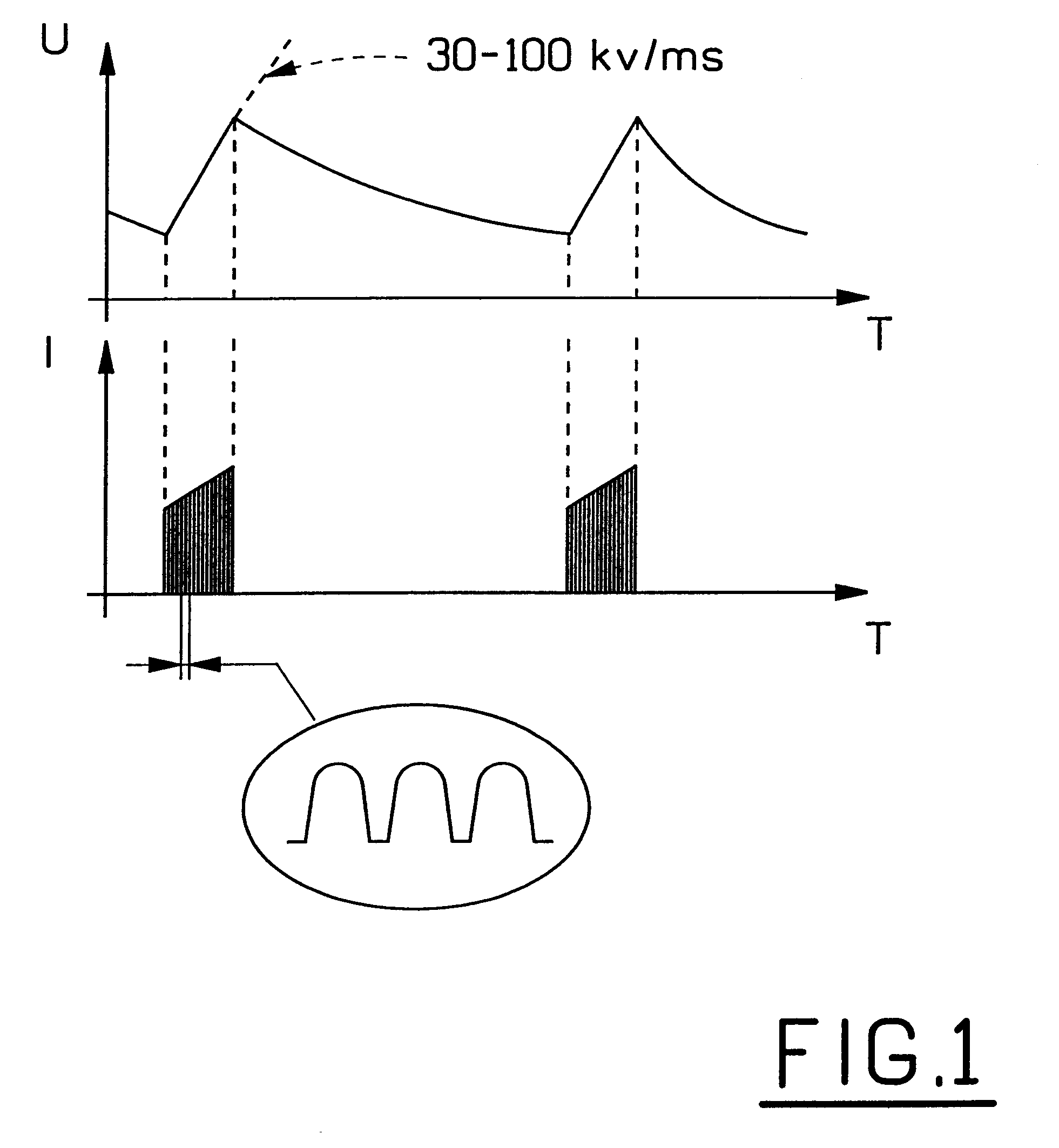
FIG. 1 shows a current-voltage diagram which is obtained in an electrostatic precipitator by virtue of the present invention. As can be seen from the drawing, voltage peaks (U) are obtained with a steep positive growth derivative and a less steep negative derivative. According to the invention, as can also be seen from FIG. 1, each voltage peak is built up by a group of current pulses. The time between each group of current pulses is referred to below as the OFF time, and the time the group of current pulses lasts is referred to below as the ON time.

It is desirable that the voltage peaks generated have as high a growth derivative as possible. The growth derivative is preferably to exceed 30 kV / ms, and so the current pulses in the groups corresponding to each voltage peak must be given such an amplitude and frequency that this derivative is achieved.

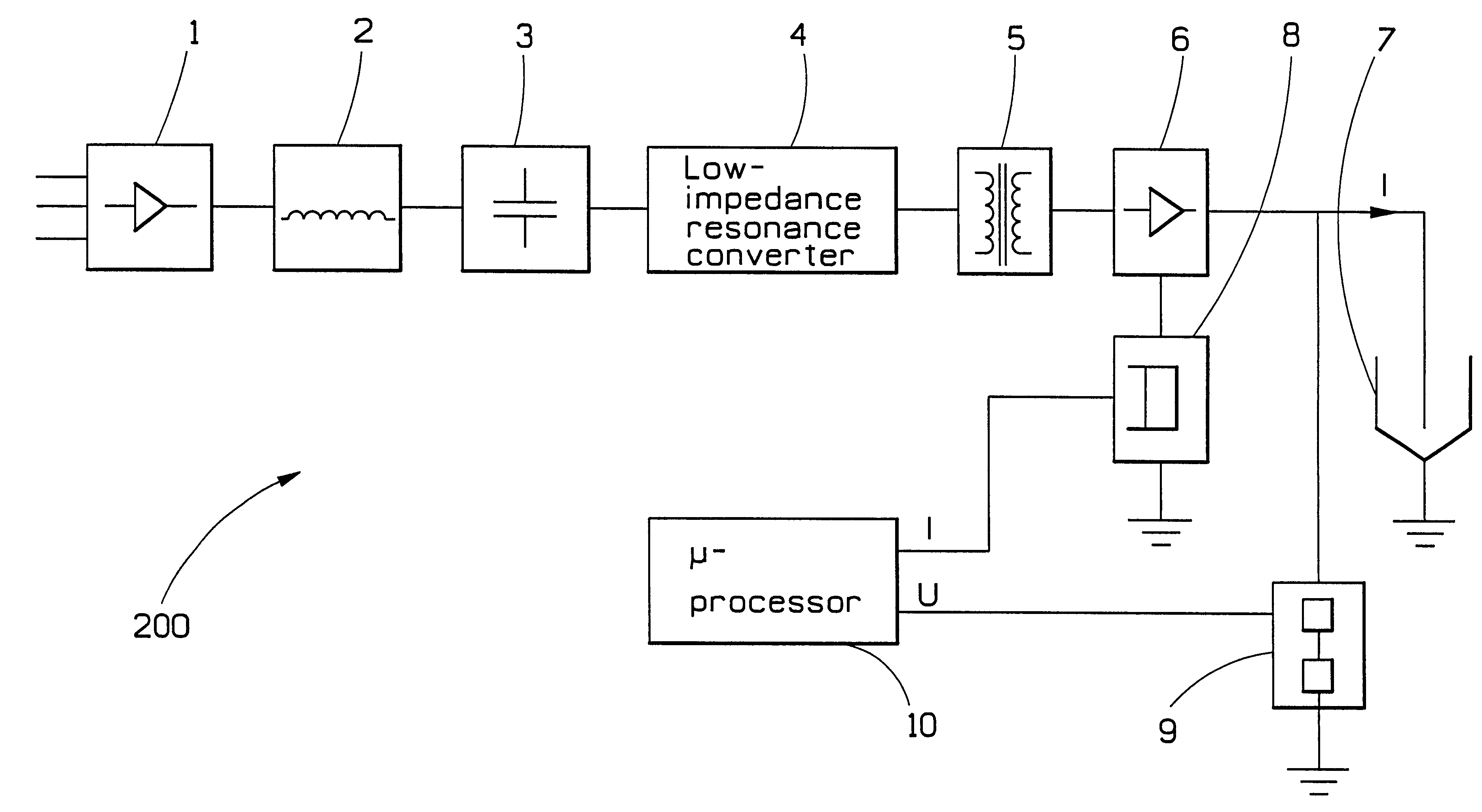
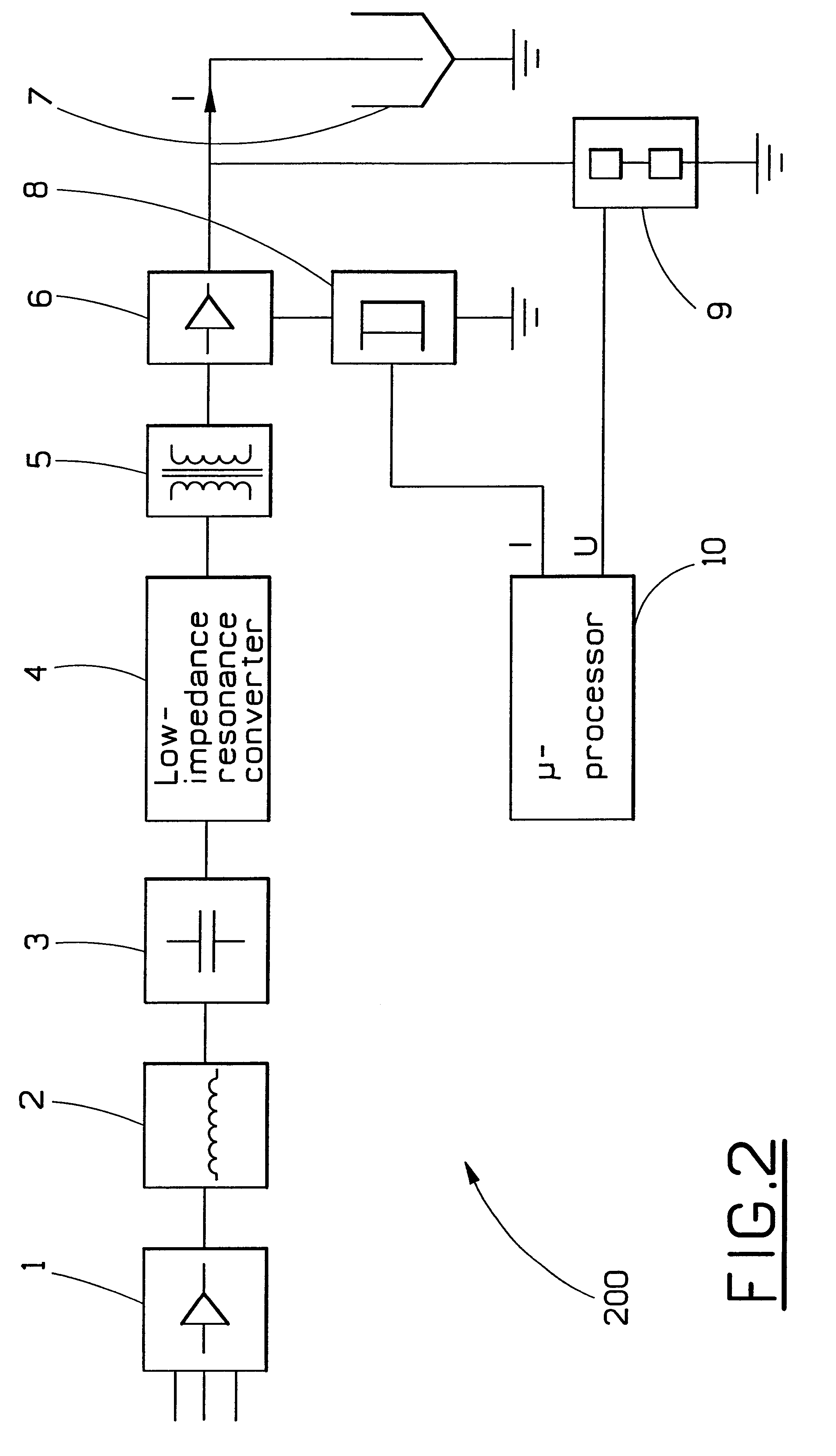
FIG. 2 shows a device 200 according to the invention, for generating groups of current pulses which in turn build up the desired individ...


PUM


Abstract

The method of invention relates to a method and device for generating voltage peaks in an electrostatic precipitator via generation of current pulse, where each voltage peak is generated by a group of current pulses. A device according to the invention comprises a first and a second means for converting alternating current to direct current, and also so first means for converting direct current to alternating current, and the first means for converting direct current to alternating current comprises a resonance converter.

Description

1. Field of the InventionThe present invention relates to a method and a device for generating voltage peaks in electrostatic precipitators, in particular those electrostatic precipitators which are used for purification in power stations and similar installations, the gas discharges of which contain dust particles.2. Description of Related ArtOne way of separating dust particles from a gas is to use an electrostatic dust precipitator, sometimes also referred to as an ESP or an electrostatic precipitator. Examples of common areas of application of electrostatic precipitators are coal-fired power stations, cement factories and refuse incineration.As is clear from the name, an electrostatic precipitator makes use of electrostatic forces to separate dust particles from a gas. Broadly speaking, this is effected in the following manner: the gas is led into a chamber which contains vertical metal curtains which divide the chamber into a number of parallel gas passages. Arranged centrally ...

Claims


Application Information

Patent Timeline
Patent Type & Authority Patents(United States)
IPC IPC(8): B03C3/66B03C3/68
CPCB03C3/68Y10S323/903
Inventor WALLGREN, BERNTWRAMDEMARK, ANDREAS
Owner KRAFTELEKTRONIK
Why Eureka
Try Eureka