
Circuits, Architectures, Apparatuses, Methods and Algorithms for Determining a DC Bias in an AC or AC-Coupled Signal

a technology of ac-coupled signals and components, applied in the direction of resistance/reactance/impedence, instruments, spectral/fourier analysis, etc., can solve the problems of circuitry not always accurately detecting the dc level of the ac-, inaccurate er values, and inaccurate er values, etc., to achieve accurate or precise dc level determination, accurate or precise dc level

Active Publication Date: 2013-02-14
SOURCE PHOTONICS
View PDF7 Cites 11 Cited by
  • Summary
  • Abstract
  • Description
  • Claims
  • Application Information

AI Technical Summary

Benefits of technology

The present invention is about a way to make sure that the voltage level of an output from a circuit is accurate. This is useful for making sure that the circuit is working well and can produce consistent results.

Problems solved by technology

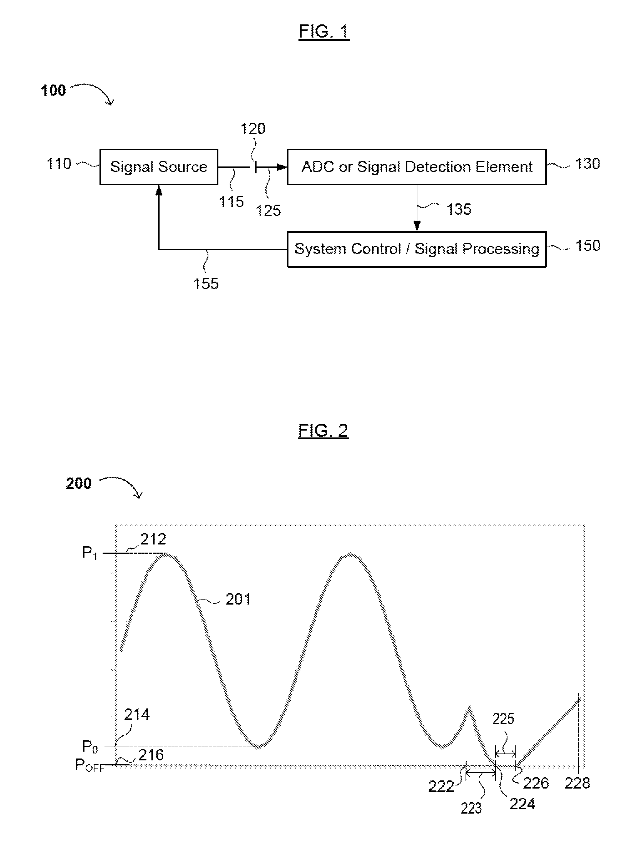
Thus, utilizing an inaccurate POFF value in Equation [1] can result in the denominator having a calculated value significantly different from the actual value, resulting in inaccurate ER values.
However, such methods may inaccurately determine the off-state power (e.g., POFF) as having the same value as that of the zero-level power (P0), resulting in an inaccurate ER value (e.g., an ER value calculated using Equation [1]).
That is, such methods and circuitry do not always accurately detect the DC level of the AC-coupled signal that is introduced by the AC-coupled circuit itself.
Such methods can cause detrimental effects to the signal quality of the received AC signal, especially in high-frequency or high data-rate systems, resulting in inaccurate DC level determinations.
Additionally, such techniques can add unwanted complexity to a product including the AC-coupled circuitry.
Thus, although DC-coupled designs can greatly simplify the measurement of the DC component or DC offset, such designs add greater complexity in the AC performance of the system.
For example, utilizing a DC probe to determine a DC level may result in an inaccurate DC voltage measurement due to the internal circuitry of the DC probe.
The forward voltage drop (e.g., about 0.70V) of an internal diode in the DC probe may limit accurate measurements of voltages less than or about equal to the forward voltage drop of the diode.
Additionally, DC component measurements utilizing a signal tap or additional circuitry (e.g., a DC mirror circuit) may decrease the accuracy of the measurement due to the introduction of additional loads (e.g., impedance) or noise on the AC-coupled circuitry.

Method used


Image

  • Circuits, Architectures, Apparatuses, Methods and Algorithms for Determining a DC Bias in an AC or AC-Coupled Signal
  • Circuits, Architectures, Apparatuses, Methods and Algorithms for Determining a DC Bias in an AC or AC-Coupled Signal
  • Circuits, Architectures, Apparatuses, Methods and Algorithms for Determining a DC Bias in an AC or AC-Coupled Signal

Examples


Embodiment Construction

[0021]Reference will now be made in detail to various embodiments of the invention, examples of which are illustrated in the accompanying drawings. While the invention will be described in conjunction with the following embodiments, it will be understood that the descriptions are not intended to limit the invention to these embodiments. On the contrary, the invention is intended to cover alternatives, modifications and equivalents that may be included within the spirit and scope of the invention as defined by the appended claims. Furthermore, in the following detailed description, numerous specific details are set forth in order to provide a thorough understanding of the present invention. However, it will be readily apparent to one skilled in the art that the present invention may be practiced without these specific details. In other instances, well-known methods, procedures, components, and circuits have not been described in detail so as not to unnecessarily obscure aspects of th...


PUM


Abstract

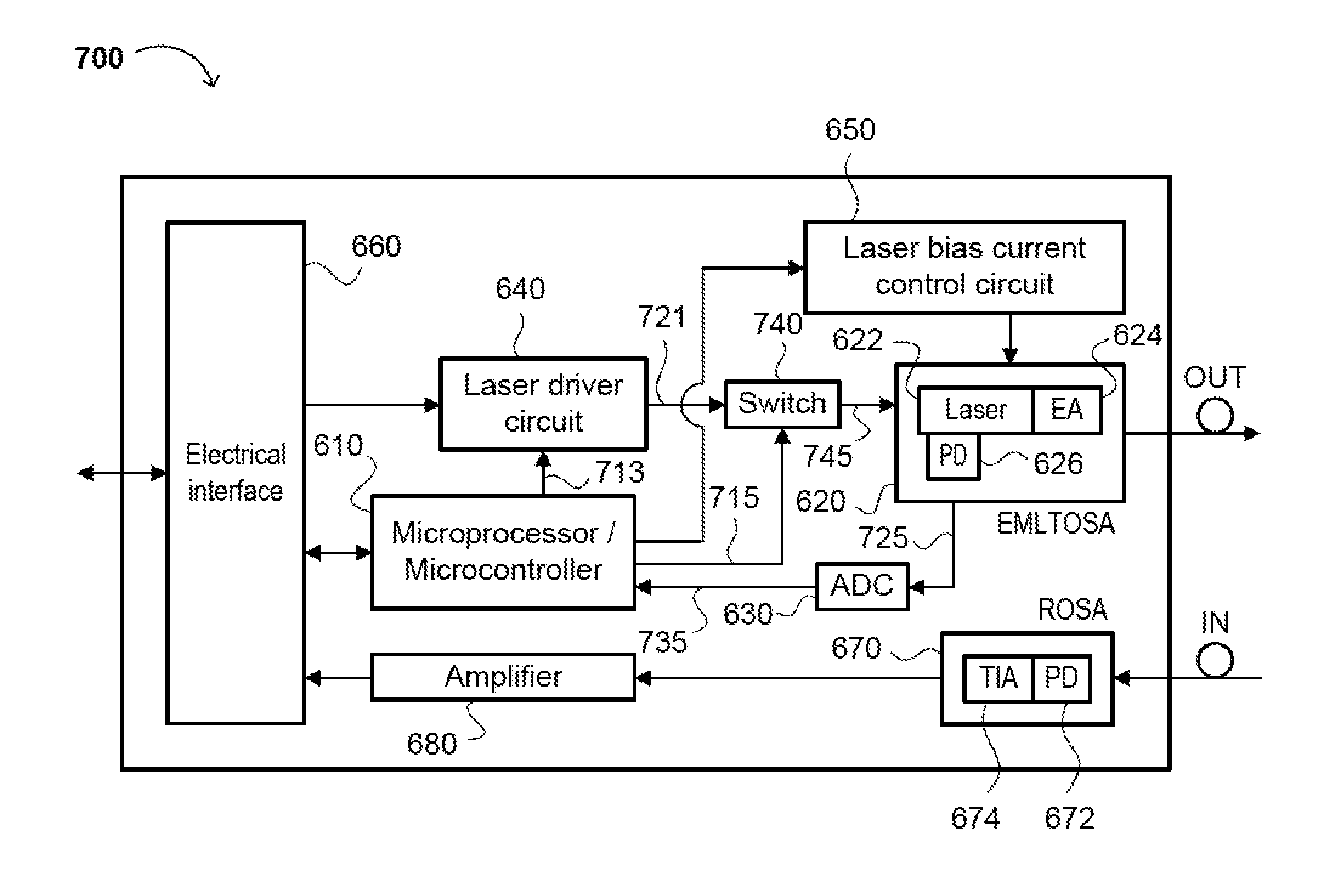
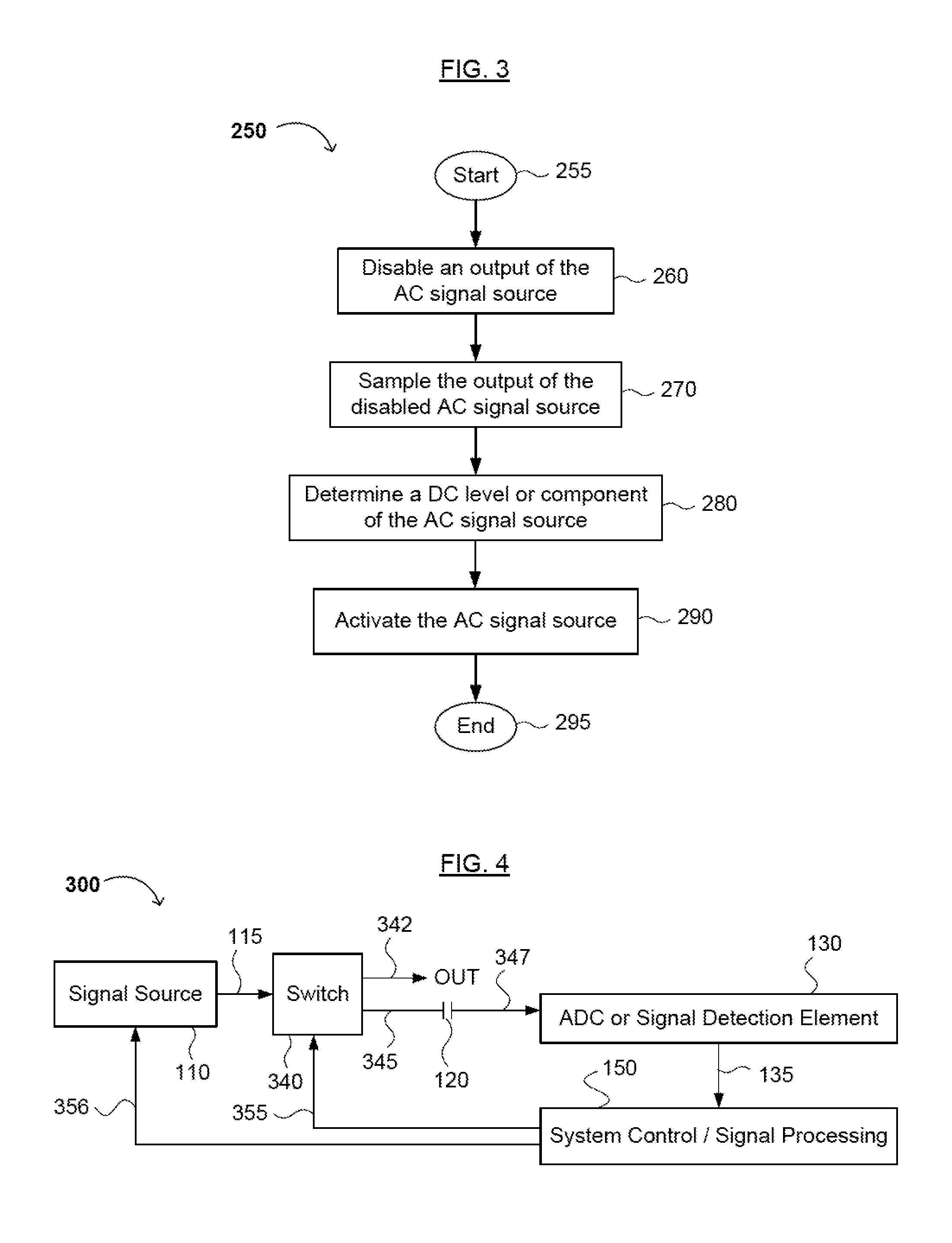
Methods, circuits, architectures, apparatuses, and algorithms for determining a DC level in an AC or AC-coupled signal. The method generally includes disabling the AC or AC-coupled signal; sampling the disabled AC or AC-coupled signal to obtain sampled DC values of the AC or AC-coupled signal; and calculating the DC level using the sampled DC values of the AC or AC-coupled signal. The present transmitter generally includes an electro-absorption modulated laser (EML); a photodetector; a signal source configured to provide an AC or AC-coupled signal to the EML; and a microcontroller or microprocessor configured to (i) control the signal source, (ii) receive information from the photodetector, and (iii) deactivate the signal source for a predetermined length of time. The circuits, architectures, and apparatuses generally include those that embody one or more of the inventive concepts disclosed herein.

Description

FIELD OF THE INVENTION[0001]The present invention generally relates to measuring a DC component of an AC or AC-coupled signal and / or a DC offset of AC signal detection circuitry in electronic circuitry. More specifically, embodiments of the present invention pertain to methods, circuits, architectures, apparatuses, and algorithms for determining a DC level in an AC or AC-coupled signal and / or a DC offset in AC signal detection and / or processing circuitry, and calculating a value of one or more parameters based on the DC level.DISCUSSION OF THE BACKGROUND[0002]In circuitry that receives an AC signal (“AC-coupled circuitry”), a DC component of a complex wave (i.e., one containing both AC and DC components) is a current component that has an unchanging polarity. That is, the DC component is the mean (average) value at which the AC component(s) alternate, pulsate, or fluctuate. An AC waveform with a zero DC component (i.e., an AC waveform having an average value of zero) is known as a D...

Claims


Application Information

Patent Timeline
IPC IPC(8): H04B10/02G01R29/00
CPCG01R19/2506
Inventor LABOUNTY, CHRISROPE, TODDCIPLICKAS, TOMAS J.MARGALIT, NEAR
Owner SOURCE PHOTONICS
Learn More