Surgical Rongeur Release Mechanism

a release mechanism and surgical technology, applied in the field of surgical rongeurs, can solve the problems of unfettered access between the slide and the shaft, cross-contamination events, and parts that can be lost during cleaning and sterilization,

Inactive Publication Date: 2013-02-14
VIKON SURGICAL
View PDF7 Cites 67 Cited by
  • Summary
  • Abstract
  • Description
  • Claims
  • Application Information

AI Technical Summary

Benefits of technology

[0007]The present invention is directed to a convertible Kerrison rongeur that can be partially disassembled for exposing the sliding surfaces of the rongeur for thorough cleaning while remaining compact and as a single piece. This is accomplished by providing the rongeur with a hinging element having a pivot axis that extends parallel to the functional length of the rongeur. Such an arrangement allows a top cutting slide of the rongeur to flip between an open position where the cutting slide is located off to one side of the rongeur and a closed position.

Problems solved by technology

Since the accumulated materials are often difficult to remove, subsequent uses of an improperly cleaned rongeur can result in cross-contamination events.
A drawback of the device is that the parts can become lost during cleaning and sterilization.
However, this gap is not sufficiently wide to allow unfettered access between the slide and shaft by brushes for thorough cleaning.
Further, the distal portions of the cutting side and stationary shaft remain in contact where the accumulated materials cannot be easily cleaned out.
Although the converted devices remain assembled in a single piece since the cutting slides are left dangling in an open position, the devices tend to occupy more space in the sterilization chamber than they do in the closed position and increase the likelihood of the cutting slide becoming bent or otherwise damaged.

Method used


Image

  • Surgical Rongeur Release Mechanism
  • Surgical Rongeur Release Mechanism
  • Surgical Rongeur Release Mechanism

Examples


Embodiment Construction

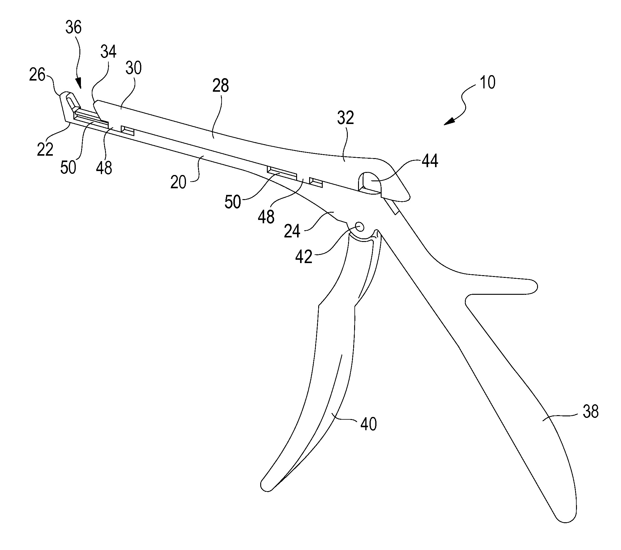
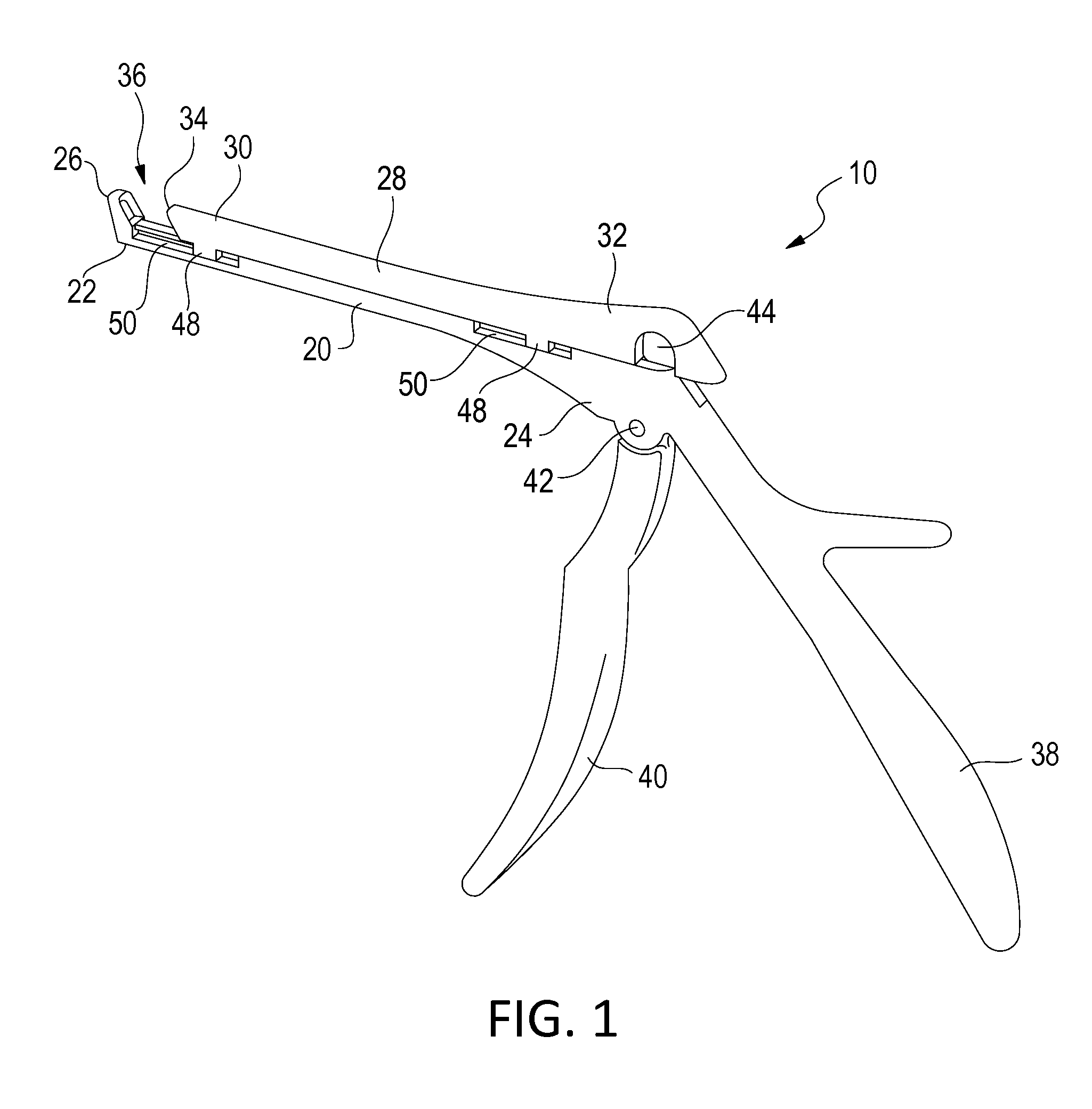
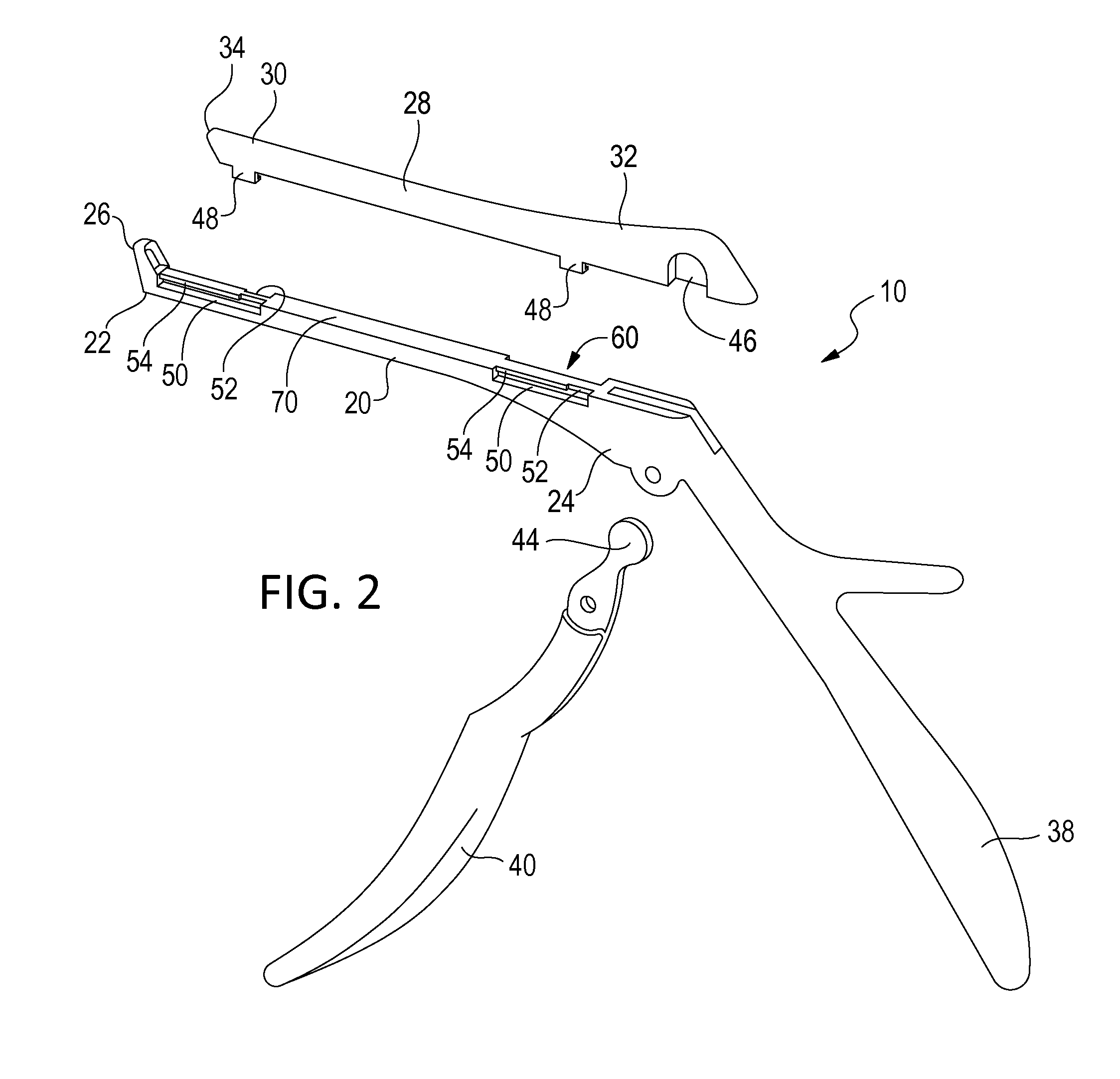
[0047]FIGS. 1 through 8 illustrate a surgical rongeur 10 in accordance with a preferred embodiment of the present invention. A rongeur 12 in accordance with another preferred embodiment of the present invention is illustrated in FIGS. 9 through 14, where like features share like numbering with FIGS. 1 through 8. FIGS. 15 through 23 illustrate a rongeur release mechanism 100 in accordance with a preferred embodiment of the present invention. FIGS. 24 through 28 illustrate a rongeur release mechanism 200 in accordance with another preferred embodiment of the present invention. A rongeur release mechanism 300 in accordance with yet another preferred embodiment of the present invention is illustrated in FIGS. 30 through 33. In FIGS. 15 through 33, like features share like numbering with FIGS. 1 through 8.

[0048]Referring to FIGS. 1 through 14, each of rongeurs 10 and 12 generally includes a stationary shaft 20 having a distal end 22, a proximal end 24 and a foot plate 26. A cutting slide...


PUM


Abstract

A rongeur including a shaft having a foot plate, a cutting slide, a breach extending between the foot plate and the cutting slide and a handle assembly for moving the cutting slide along the shaft. The cutting slide includes a pair of tracking arms arranged about a distal end of the cutting slide and a third tracking arm arranged about the proximal end thereof. The tracking arms are received within corresponding tracking slots in the shaft when the rongeur is in a closed position. The tracking arms are disengaged from the tracking slots by rotating the cutting slide about a pivot axis that extends parallel to the length of the shaft thereby placing the rongeur in an open position. To prevent inadvertent disengagement of the tracking arms from the tracking slots, a trigger assembly is provided which arrests proximal movement of the cutting slide.

Description

CROSS-REFERENCES TO RELATED APPLICATIONS[0001]This application is a continuation in part of and claims priority to U.S. provisional application Ser. No. 61 / 524,452 filed on Aug. 17, 2011, U.S. provisional application Ser. No. 61 / 523,952 filed on Aug. 16, 2011, and U.S. non-provisional application Ser. No. 13 / 083,742 filed on Apr. 11, 2011, which claims priority to U.S. provisional application Ser. No. 61 / 438,754 filed on Feb. 2, 2011, the disclosures of which are incorporated herein by reference in their entireties for any and all purposes.FIELD OF THE INVENTION[0002]This invention relates generally to surgical rongeurs, and more particularly to release mechanisms for Kerrison-style rongeurs used in laminectomies and laminotomies.BACKGROUND OF THE INVENTION[0003]Kerrison rongeurs are utilized in spinal surgery to remove bone and tissue and thereby gain access to the spinal canal. Kerrison rongeurs typically comprise a stationary shaft and a cutting slide that is longitudinally slida...

Claims


Application Information

Patent Timeline
Patent Type & Authority Applications(United States)
IPC IPC(8): A61B17/16
CPCA61B17/1611
Inventor BODOR, PETER PALYE, SHUSHENGSCHONLAU, LEIGHTONBODOR, ZOLTAN A.BUSH, DAVID
Owner VIKON SURGICAL
Why Eureka
Try Eureka