
Travel support apparatus and travel support system

a technology of travel support and support system, which is applied in the direction of vehicle position/course/altitude control, process and machine control, instruments, etc., can solve the problems of destroying the advantages of convoy travel, affecting the speed control capacity, and reducing the speed of the vehicl

Active Publication Date: 2013-02-14
DENSO CORP
View PDF4 Cites 93 Cited by
  • Summary
  • Abstract
  • Description
  • Claims
  • Application Information

AI Technical Summary

Benefits of technology

The patent text describes a travel support system for vehicles that can adjust the distance between them to improve convoy travel. The system includes a communication unit, sensors, and a control unit. The system can detect the distance between the subject vehicle and the lead vehicle, and adjust the speed and distance to reduce the time it takes for the subject vehicle to slow down to the desired speed. This improves the overall travel experience for all vehicles in the convoy.

Problems solved by technology

However, conventionally, it is difficult to reduce the inter-vehicle distance in the convoy travel of the vehicles, thereby making it difficult to achieve the advantageous effects of the convoy travel.
Further, whether the vehicle is equipped with an independent range sensor, which independently detects an inter-vehicle distance to a lead vehicle and whether the range sensor has detected an obstacle or not are closely related to and are substantially affecting the speed control capacity such as a “distance-based” response time or the like, which is detected as a response time for reducing the vehicle speed when a detected inter-vehicle distance is too short to the lead vehicle.
When a vehicle has a lower speed control capacity, such vehicle must have a longer inter-vehicle distance to the lead vehicle, because such vehicle takes a longer time to reduce its speed to a target value.
Therefore, depending on the vehicles, such target inter-vehicle distance is too long, and the advantages of the convoy travel of the vehicles were destroyed.

Method used


Image

  • Travel support apparatus and travel support system
  • Travel support apparatus and travel support system
  • Travel support apparatus and travel support system

Examples


Embodiment Construction

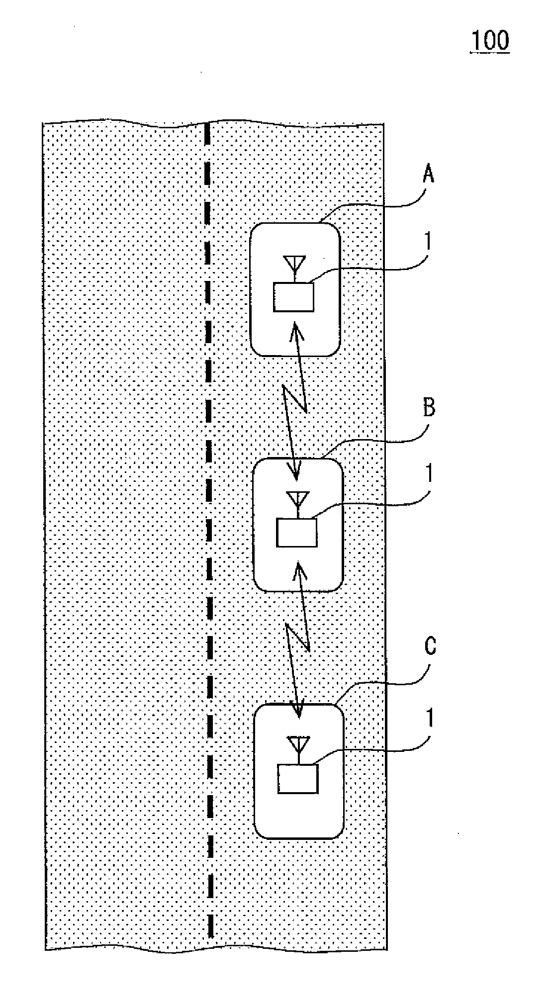
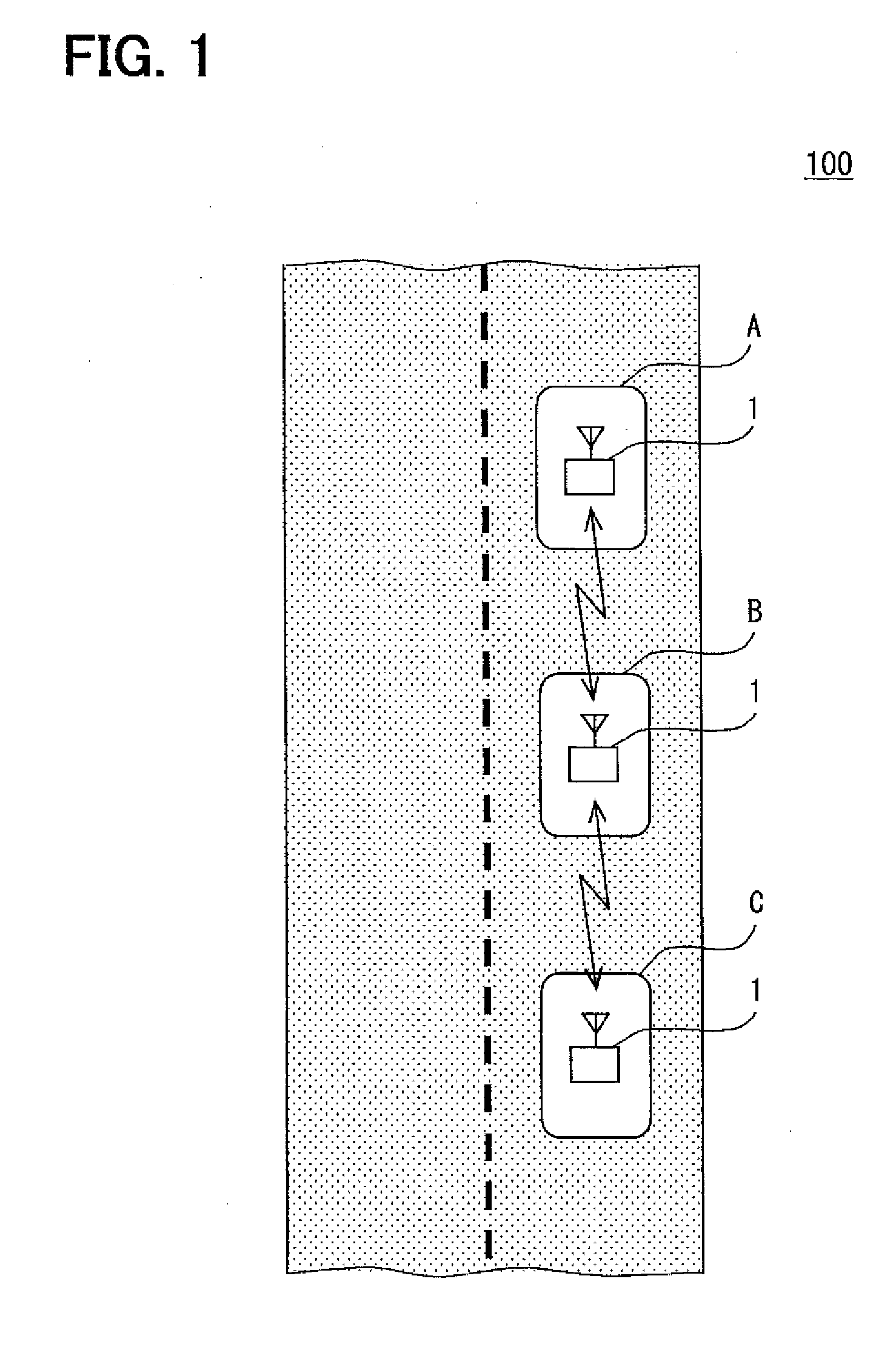
[0037]The embodiment of the present disclosure is described with reference to the drawings. FIG. 1 is an illustration of a travel support system 100 of the present disclosure. The travel support system 100 in FIG. 1 includes multiple travel support apparatuses 1 respectively installed in multiple vehicles (i.e., vehicles A-C), where one travel support apparatus 1 is installed in each of the vehicles A,B,C.

[0038]The configuration of FIG. 1, which includes three travel support apparatuses 1 in one travel support system 100, may be modified to include four or more apparatuses 1 in one travel support system 100, or only one or two apparatuses 1 in one travel support system 1, and is not limited to the three travel support apparatuses 1 depicted.

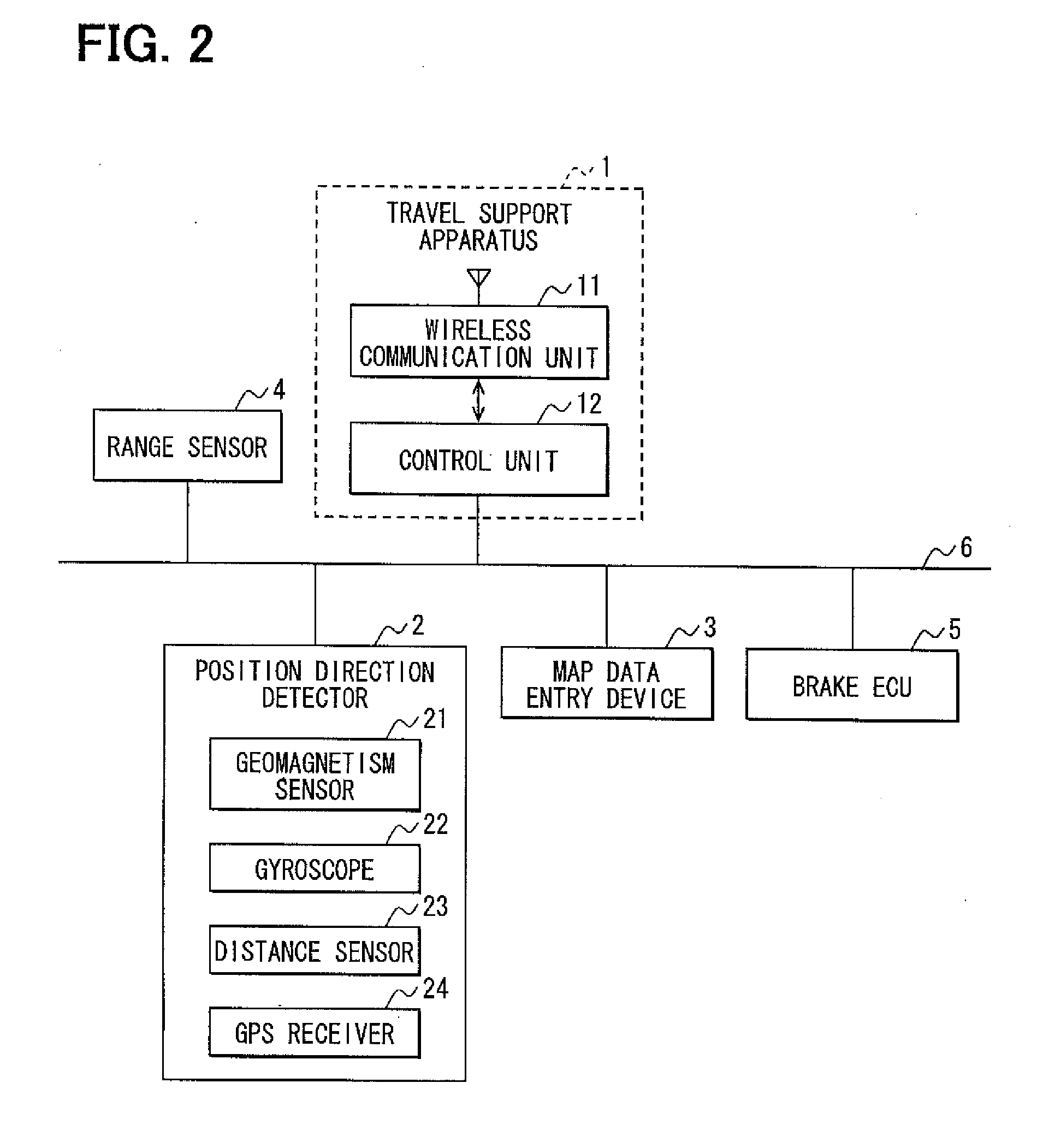
[0039]With reference to FIG. 2, the travel support apparatus 1, which is disposed in each of the vehicles includes a wireless communication unit 11 and a control unit 12. Further, the travel support apparatus 1 is communicably coupled to componen...


PUM


Abstract

A travel support system uses a wireless communication unit for receiving a following vehicle's speed control capacity, and compares the speed control capacity received with a speed control capacity of the subject vehicle. If the speed control capacity of the following vehicle is higher than the capacity of the subject vehicle, a maximum deceleration of the subject vehicle is restricted to a restricted value. In addition, a target inter-vehicle distance to a lead vehicle is set according to the restricted value of the subject vehicle, thereby enabling a reduction of the inter-vehicle distance to the lead vehicle for each of the vehicles in a convoy.

Description

CROSS REFERENCE TO RELATED APPLICATION[0001]The present application is based on and claims the benefit of priority of Japanese Patent Application No. 2011-175092, filed on Aug. 10, 2011, the disclosure of which is incorporated herein by reference.TECHNICAL FIELD[0002]The present disclosure generally relates to a travel support apparatus and a travel support system including the travel support apparatus.BACKGROUND[0003]Conventionally, a technique for organizing a convoy travel of vehicles, or a platoon travel of vehicles, is known. The convoy travel of vehicle may include a lead vehicle and following vehicles, where a technique for organizing the convoy may control the travel of the following vehicles based on exchange of information through vehicle-to-vehicle wireless communication between terminals on the respective vehicles, for keeping a certain inter-vehicle distance interposed between vehicles. For example, Japanese Patent Laid-Open No. 2000-348300 (JP '300) discloses a convoy ...

Claims


Application Information

Patent Timeline
IPC IPC(8): G05D1/00
CPCB60T7/22B60W30/09B60W30/0956B60W30/16B60W2720/10B60W2550/30B60W2550/302B60W2550/308G08G1/22B60W2554/804B60W2554/80B60W2554/801B60W2556/65B60W2554/802
Inventor YAMASHIRO, TAKAHISA
Owner DENSO CORP
Learn More