Fluid-tight cable bushing for ribbon cable
a ribbon cable and cable bushing technology, applied in the direction of electrical equipment, etc., can solve the problems of limited dimensions and achieve the effect of convenient installation
- Summary
- Abstract
- Description
- Claims
- Application Information
AI Technical Summary
Benefits of technology
Problems solved by technology
Method used
Image

Examples
first embodiment
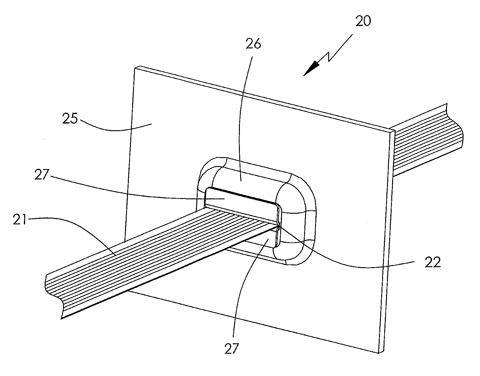
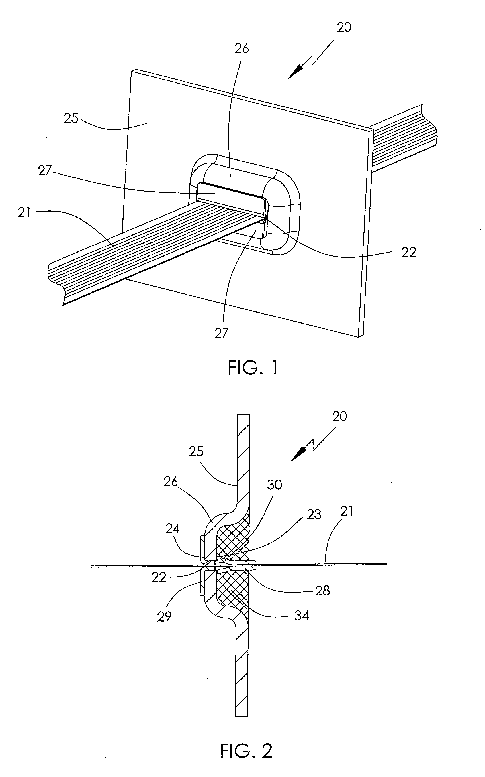
[0043]FIG. 1 shows the cable bushing 20 according to the present invention, in the installed state in cooperation with the penetration element 25. The penetration element is the housing, wall, etc., having an opening through which the ribbon cable must pass in a fluid-tight manner. FIG. 2 is a sectional view of the cable bushing 20 of FIG. 1. The fluid-tight cable bushing 20 guides the ribbon cable 21, through the opening 22 of the penetration element 25. The penetration element has a recess or shaping forming a depression 26 on a first end 23 of the opening. The cable bushing 20 has two profile supports 27 in the form of profile supports 27 with a first flange 28 having a snap-on element 30, see FIG. 3, and a second flange 29 angled from it. In the installed state the first flanges 28 of the two L-profile supports 27 extend symmetric to each other in the direction of the longitudinal axis of the ribbon cable 21 and enclose the ribbon cable 21 sandwich-like on both sides with surfac...
second embodiment
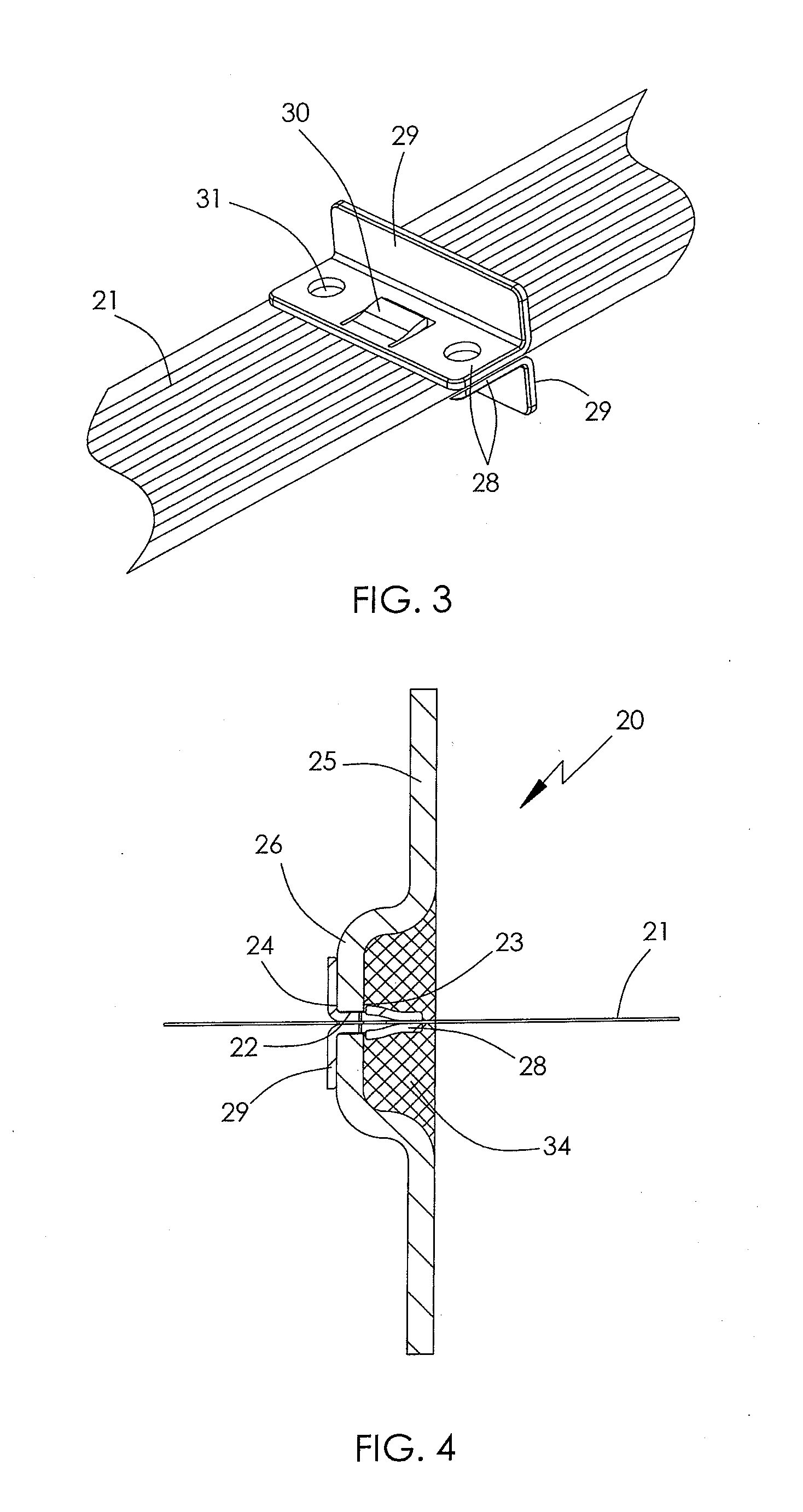
[0045]FIG. 4 is a sectional view of the cable bushing 20 according to a In principle, the structure of the cable bushing 20 depicted here corresponds to that of FIG. 2. As is apparent, the first flanges 28 of the two L-profile supports 27 are fully enclosed fluid-tight by the potting mass 34. The potting mass 34 in turn, fills the depression 26 so as to be flush with the surface of the penetration element 25. This requires that the potting mass 34 be neutral relative to ribbon cable 21, i.e., not chemically aggressive. In this embodiment the fluid-tightness of the cable bushing 20 is also guaranteed especially at very high pressure and the stability is additionally increased.
third embodiment
[0046]FIG. 5 shows a cable bushing according to a The potting mass filling the depression and the ribbon cable are omitted to show details of the cable bushing. Whereas the first flanges 28 of the L-profile supports 27 in FIGS. 1 to 4 with their snap-on elements 30 are positioned in the area of the depression 26 and are then covered fluid-tight by the potting mass 34, in the example depicted here, on the other hand, the second flanges 29 of L-profile supports 27 extending fin-like are closed by the potting mass 34 fluid-tight, especially gas-tight. This means the two L-profile supports 5 are introduced relative to the variant according to FIG. 2 from the other side of the penetration element 25. Regardless of the chosen arrangement, either the snap-on elements 30 of the first flanges 28, see FIGS. 1, 2 and 4, or their second flanges 29 extending fin-like of the L-profile supports 27, see FIG. 5, are closed gas-tight by the potting mass 34 introduced to the depression 26. The pottin...
PUM
 Abstract
Description
Claims
Application Information
 - R&D Engineer
- R&D Manager
- IP Professional
- Industry Leading Data Capabilities
- Powerful AI technology
- Patent DNA Extraction
Browse by: Latest US Patents, China's latest patents, Technical Efficacy Thesaurus, Application Domain, Technology Topic.
© 2024 PatSnap. All rights reserved.Legal|Privacy policy|Modern Slavery Act Transparency Statement|Sitemap