Magnetic storage device with humidity control device incorporating a differentially permeable membrane

a technology of humidity control device and magnetic storage device, which is applied in the field of magnetic storage device, can solve the problems of high humidity, high opening force, and actuated valves that add cost and complexity to the hdd, and achieve the effect of fast ra

Active Publication Date: 2013-02-21
WESTERN DIGITAL TECH INC
View PDF8 Cites 8 Cited by
  • Summary
  • Abstract
  • Description
  • Claims
  • Application Information

AI Technical Summary

Benefits of technology

[0011]Advantageously, embodiments of the invention provide for a laminate that would permit water to diffuse at different rates depending on which side of the laminate is proximate to the higher concentration of water. Laminates of embodiments may be used to construct a desiccant device for enclosing a desiccant material. The desiccant device of an embodiment permits water to diffuse into the desiccant device at a faster rate than water is permitted to diffuse out of the desiccant device. In certain embodiments, the rate of which water vapor may diffuse out of the desiccant device is equal to or approximates the rate at which water vapor may diffuse out of the electronic equipment in which the desiccant device is disposed, thereby ensuring that the amount of water vapor within the interior of the electronic equipment does not exceed a certain threshold.

Problems solved by technology

This property poses a problem in that if the desiccant has absorbed moisture during the storage of either the HDD itself or a system in which the HDD is installed, then the desiccant will act to maintain the humidity after the HDD is placed into operation.
However, once loaded with water, the desiccant will then cause the humidity to remain high when the HDD is placed into service.
In principle, one can use a suitably actuated valve to bypass the breather diffusion restricting channel; however, such an actuated valve would add cost and complexity to the HDD.
Further, flat “flapper” type valves are notoriously prone to sticking and would require high opening force after some time closed.

Method used


Image

  • Magnetic storage device with humidity control device incorporating a differentially permeable membrane
  • Magnetic storage device with humidity control device incorporating a differentially permeable membrane
  • Magnetic storage device with humidity control device incorporating a differentially permeable membrane

Examples


Embodiment Construction

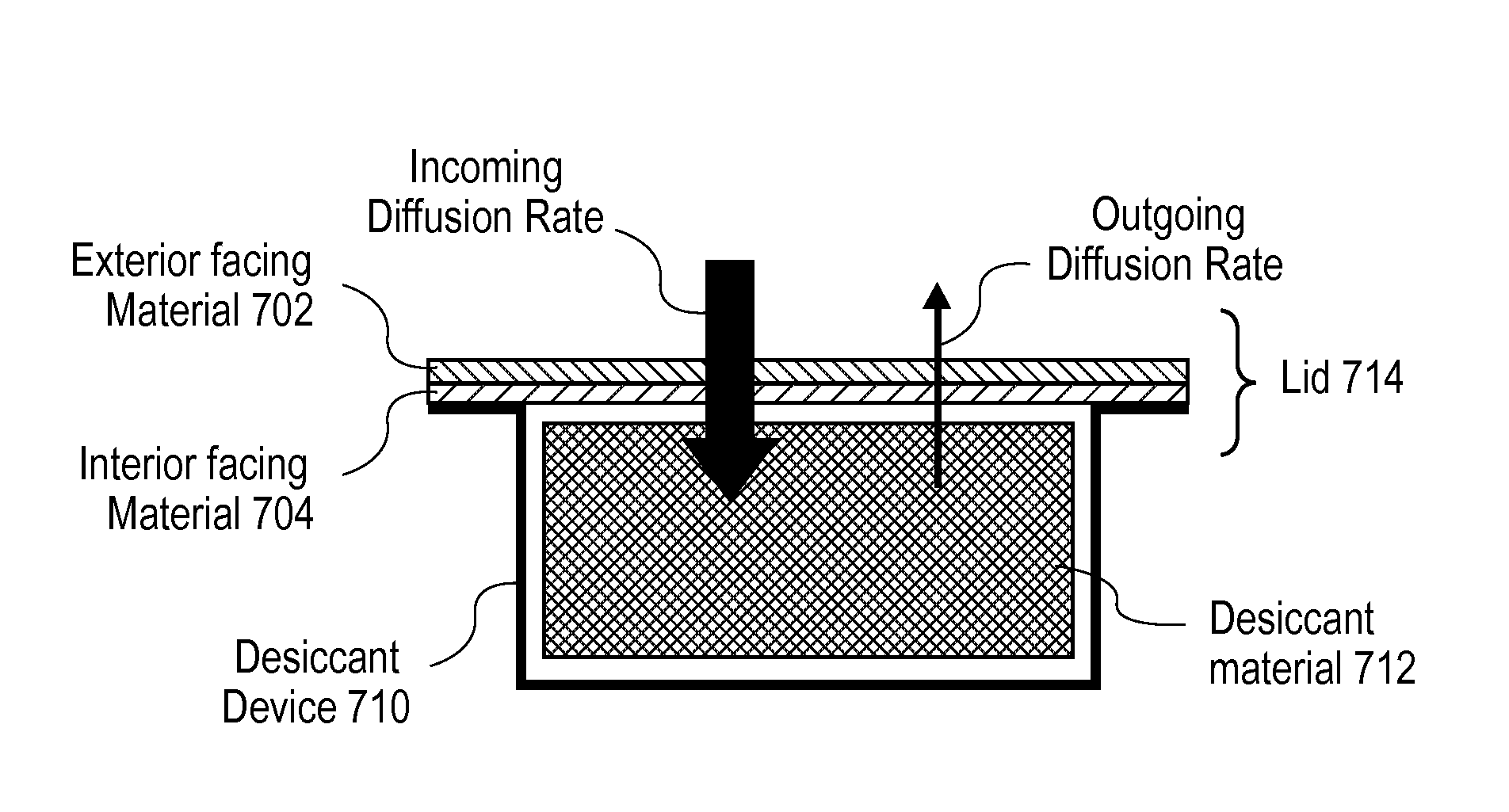
[0024]Approaches for a desiccant device for use within electronic equipment are described. The desiccant device permits water to diffuse into the desiccant device at a faster diffusion rate than water is permitted to diffuse out of the desiccant device. Embodiments may be used to prevent the desiccant material enclosed within the desiccant device from releasing large amounts of humidity into the interior of the electronic equipment. In the following description, for the purposes of explanation, numerous specific details are set forth in order to provide a thorough understanding of the embodiments of the invention described herein. It will be apparent, however, that the embodiments of the invention described herein may be practiced without these specific details. In other instances, well-known structures and devices are shown in block diagram form in order to avoid unnecessarily obscuring the embodiments of the invention described herein.

Physical Description of Illustrative Embodimen...


PUM

PropertyMeasurementUnit
running temperatureaaaaaaaaaa
absolute humidityaaaaaaaaaa

Abstract

Approaches for desiccant device within an enclosure protecting sensitive electronic equipment. Electronic equipment, such as a hard-disk drive (HDD), may comprise a desiccant device that possesses a water vapor permeability rate that matches or is substantially similar to the water vapor permeability rate of the enclosure. In this way, desiccant devices may prevent the desiccant material enclosed within from releasing large amounts of humidity into the interior of the electronic equipment. The desiccant device may be constructed using a laminate material that comprises an interior facing material and an exterior facing material. The exterior facing material permits water to diffuse faster therethrough than the interior facing material.

Description

RELATED APPLICATION DATA[0001]This application is related to U.S. patent application Ser. No. ______ (Attorney docket no. HGST.P053), entitled “Magnetic Storage Device with Dynamic Humidity Control System to Mitigate Water Vapor Transients,” invented by Charles Allan Brown et al., hereafter referred to as “the Brown patent application,” filed the same day herewith, the disclosure of which is incorporated by reference in its entirety for all purposes as if fully set forth herein.[0002]This application is related to U.S. patent application Ser. No. ______ (Attorney docket no. HGST.P055), entitled “Magnetic Storage Device with Multi-Functional Component for Controlling Chemical and Water Vapor Therein,” invented by Charles Allan Brown, filed the same day herewith, the disclosure of which is incorporated by reference in its entirety for all purposes as if fully set forth herein.FIELD OF THE INVENTION[0003]Embodiments of the invention generally relate to a desiccant device, for use in a ...

Claims


Application Information

Patent Timeline
Patent Type & Authority Applications(United States)
IPC IPC(8): G11B33/14B01D53/02
CPCG11B25/043B01D53/261G11B33/1453
Inventor BROWN, CHARLES ALLAN
Owner WESTERN DIGITAL TECH INC
Why Eureka
Try Eureka