Interchangeable display assembly

a technology of display assembly and assembly, which is applied in the direction of identification means, instruments, lighting and heating apparatus, etc., can solve the problems of increasing the number of parts, increasing the cost of custom display, and modifying the display

Inactive Publication Date: 2013-02-21
ACCESS BUSINESS GRP INT LLC
View PDF3 Cites 9 Cited by
  • Summary
  • Abstract
  • Description
  • Claims
  • Application Information

AI Technical Summary

Benefits of technology

[0010]In another embodiment, a method for assembling a lighted display assembly is provided, including positioning a display grid relative to at least two light sources so that the light passages defined in the display grid are each uniquely associated with at least one light source. One display screen is selected from a group of two display screens having different markings, but a substantially similar size and shape. The selected display screen is secured relative to the display grid so that the light sources illuminate the selected display screen.

Problems solved by technology

Manufacturing each variation of electronics device and appliance with a different, custom display may become expensive because of a significant increase in the number of parts, the variation in parts and the required manufacturing time.
Because the displays are typically a fixed, permanent part of the appliance, each display may require a different installation technique, which may further increase manufacturing time.

Method used


Image

  • Interchangeable display assembly
  • Interchangeable display assembly
  • Interchangeable display assembly

Examples


first embodiment

II. First Embodiment

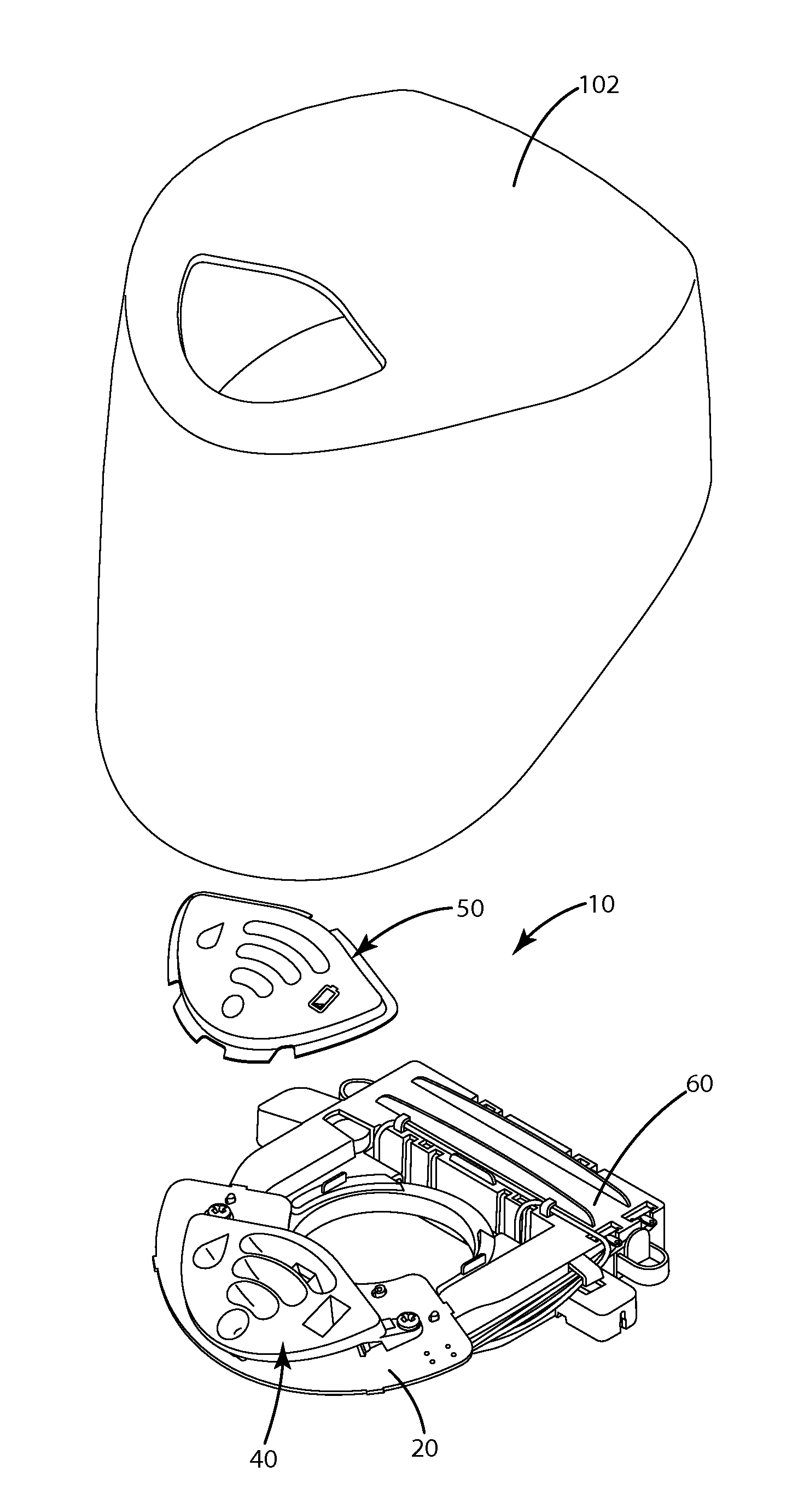
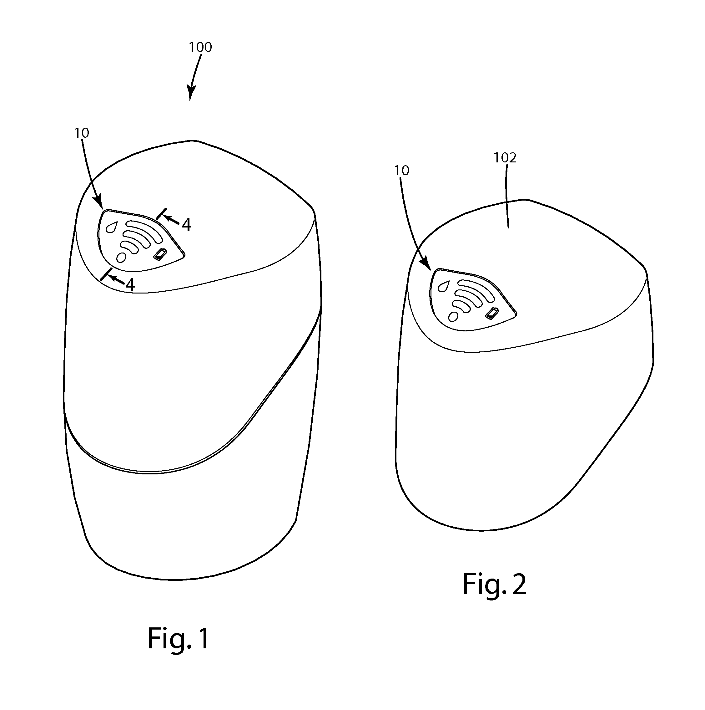
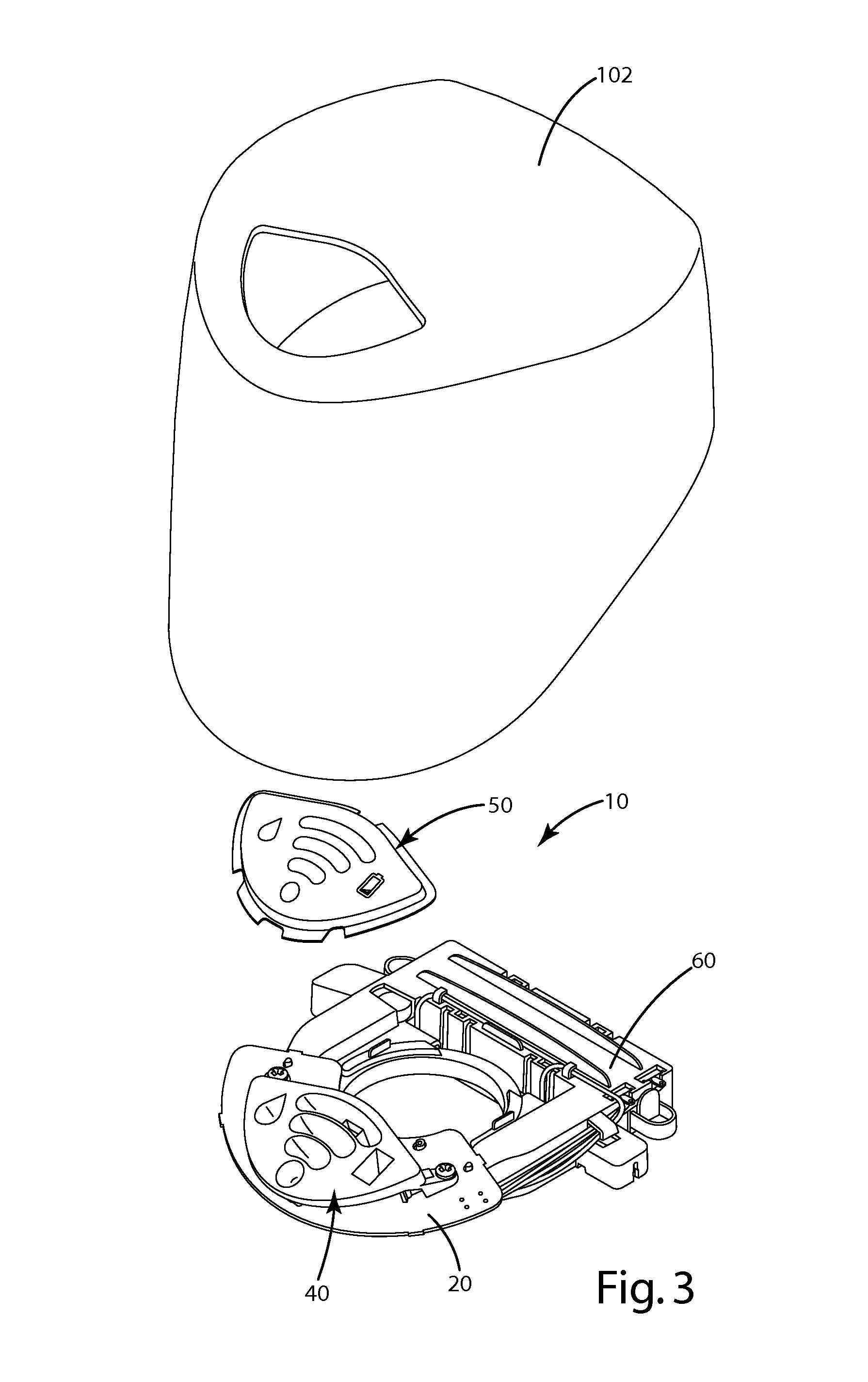
[0022]A first embodiment of the interchangeable display assembly is shown in FIGS. 1-6 and generally designated 10. As shown, the display assembly 10 is positioned within the top shroud 102 of the appliance 100 and generally includes a controller or circuit board 20, multiple light sources 30, a display grid 40 and a display screen 50.

[0023]The circuit board 20 may be connected to an electronics assembly 60 and may determine a status or state of operation of the appliance 100. The circuit board 20 may be connected to the light sources 30 and may cause one or more of the light sources 30 to flash, turn on or turn off to communicate the state of operation of the appliance 100 to the user. For example, if the appliance 100 is a home water treatment system, one light source 30 may illuminate to indicate that the system is currently treating water and another light source 30 may illuminate to indicate that the system is in a standby mode and is not currently treating ...

second embodiment

III. Second Embodiment

[0034]An interchangeable display assembly according to a second embodiment of the present invention is shown in FIGS. 7-9 and generally designated 210. The display assembly 210 is shown as part of a home appliance 200, and may indicate at least one status or state of operation of the appliance 200. For example, the home appliance may be an air treatment system and the display assembly 210 may indicate that the air treatment system is currently treating air. As with the first embodiment, it will be understood that the display assembly 210 may be installed in any of a variety of electronics and appliances, and may indicate any of a variety of statuses with regard to the appliance.

[0035]As shown in FIGS. 7-9, the display assembly 210 may be positioned behind a cover 202 of the appliance 200 and generally includes a controller or circuit board 220, multiple light sources 230, a display grid 240 and a display screen 250. The cover 202 may be transparent to allow a u...


PUM

PropertyMeasurementUnit
sizeaaaaaaaaaa
shapeaaaaaaaaaa
sizesaaaaaaaaaa

Abstract

A lighted display assembly for an appliance includes interchangeable display screens. Multiple light sources flash, turn on and turn off to indicate a status of the appliance by illuminating a selected one of the display screens. A display grid extends between the light sources and the selected display screen and defines light passages that are each uniquely associated with a corresponding light source. Light emitted by each light source is confined to a discrete area of the display screen by the corresponding light passage. The discrete areas of the interchangeable display screens may include any of a variety of markings, for example, markings in a different language. The assemblies may be tailored to the needs of a particular customer by selecting an appropriate display screen.

Description

BACKGROUND OF THE INVENTION[0001]This invention relates to display assemblies. More particularly, this invention relates to lighted display assemblies for use in electronics or appliances.[0002]Lighted displays are commonly included in many appliances to communicate various information about the appliance to a user. For example, the display may indicate whether the appliance is turned on, whether the appliance is functioning properly, or what stage or cycle the appliance is in. Often these displays are a fixed, permanent part of the appliance.[0003]As more businesses distribute products internationally to take advantage of a larger consumer base, it may become desirable to create a lighted display that is tailored for use in specific countries. For example, a washing machine sold in China may include information in the Chinese language and use common Chinese symbols and icons, while the same washing machine sold in France would likely include information in the French language and u...

Claims


Application Information

Patent Timeline
Patent Type & Authority Applications(United States)
IPC IPC(8): F21V33/00H01S4/00
CPCY10T29/49002G09F23/0058G09F7/02F21V11/06G09F3/202F21W2131/305F21V33/0044F21V11/02G09F13/04F21V11/00G09F2007/005F21W2131/307G09F13/0454G01D11/28
Inventor MILES, MICHAEL E.LAUTZENHEISER, TERRY L.VECZIEDINS, KARLIS
Owner ACCESS BUSINESS GRP INT LLC
Why Eureka
Try Eureka