Antenna with core, mainly miniature RFID and/or NFC antenna, and method of its production

a technology of rfid and/or nfc antennas, which is applied in the direction of antennas, instruments, antenna details, etc., can solve the problems of low mechanical resilience of the conductive loops during further mounting of the antenna into the circuit, prone to snapping, and worsening the emitting characteristics of the antenna, so as to achieve reliable connection

Active Publication Date: 2020-08-11
LOGOMOTION SRO
View PDF13 Cites 0 Cited by
  • Summary
  • Abstract
  • Description
  • Claims
  • Application Information

AI Technical Summary

Benefits of technology

[0009]Such arrangement allows simply solving of the technical problems common during typical winding of the solid conductor around the core. First conductive element of the loop has flat character, since it is formed by a conductive strip formed on the substrate and it is produced by a common method, such as the applied conductive paths on the PCB. During constant pitch of the thread the conductive strips on the substrate are parallel and have similar size and shape. This will usually hold with exception of first and last conductive strip; these can have a shape suitable for connection of an antenna to the circuit. If the antenna has multiple branches (digressions), the conductive strips with the produced outlets will differ compared to neighboring conductive strips. This is another advantage of the antenna according to this invention: it can be freely designed as antenna with various digressions, which are easily produced as part of conductive strips. Conductive strips can be produced directly on the PCB; in such case the antenna is produced as part of the board with other circuits. In another case the conductive strips can be produced on a surface of the chip or on the independent surface, for example a pad with the dimensions pursuant to the ground plan of the whole group of the conductive strips, whereby such pad forms a basis of the antenna as an independent component. According to this the antenna can be produced as independent component, as part of the electronic or electric component or as a part of the PCB of the host device. Conductive strips can be easily and quickly produced by contemporary technologies in such a way that they have a necessary width and form flat conductor of a single part of the loop. With the constant pitch of the thread the non-conductive gaps between the conductive strips will be usually smaller than the half of the width of the conductive strip, preferably smaller than a quarter of the width of the conductive strip. Small gaps between the neighboring conductive strips prevent the magnetic field from leaking outside the ends of the core.
[0030]The function of the air gap is to prevent oversaturation of the magnetic field in the core. The term “gap” means that it is a space where there is a material with a relative permeability approaching 1; it does not have to be a physically empty or—exactly—an air gap. The gap in form of a non-conductive layer can be produced as a plastic film below the core on the conductive strips.

Problems solved by technology

During the production of these antennas the problem lies in effective and fast winding of the conductors on the core in such a way that it achieves desired slope of the winding with a very fine conductor, or with thin flat conductor, respectively, which is prone to snapping in places of deformation.
The disadvantage during the typical production of the antenna with winding of the conductor is the low mechanical resilience of the conductive loops during further mounting of the antenna into circuits.
The solidity of the wound conductor can be increased by increasing its thickness, which with required small dimensions of the antenna is impossible, and which would also worsen the emitting characteristics of the antenna.

Method used


Image

  • Antenna with core, mainly miniature RFID and/or NFC antenna, and method of its production
  • Antenna with core, mainly miniature RFID and/or NFC antenna, and method of its production
  • Antenna with core, mainly miniature RFID and/or NFC antenna, and method of its production

Examples


example 1

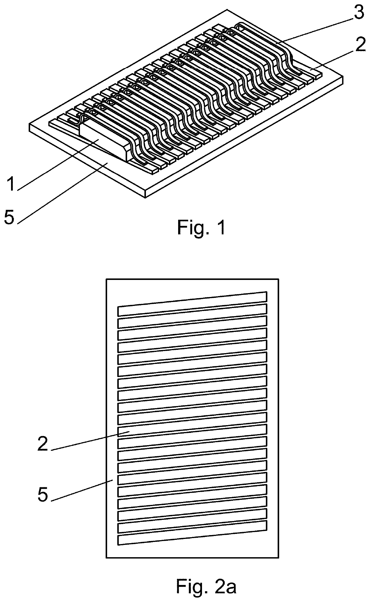
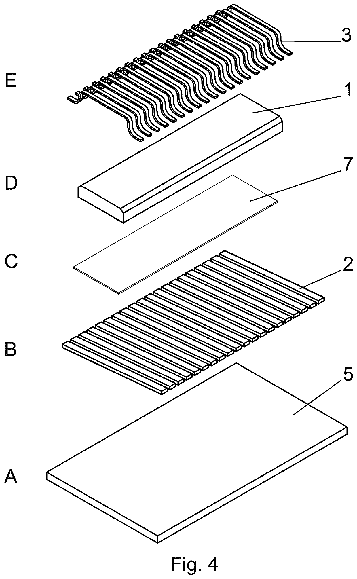
[0055]In this example according to FIGS. 1 to 4, 6, 9, 13 and 16 the antenna is produced as an independent component designed for subsequent mounting on the PCB. The antenna has a ferrite core 1 with flat rectangular cross-section. The core 1 is 9 mm long and its rectangular cross-section has dimensions 2.4 mm×0.3 mm.

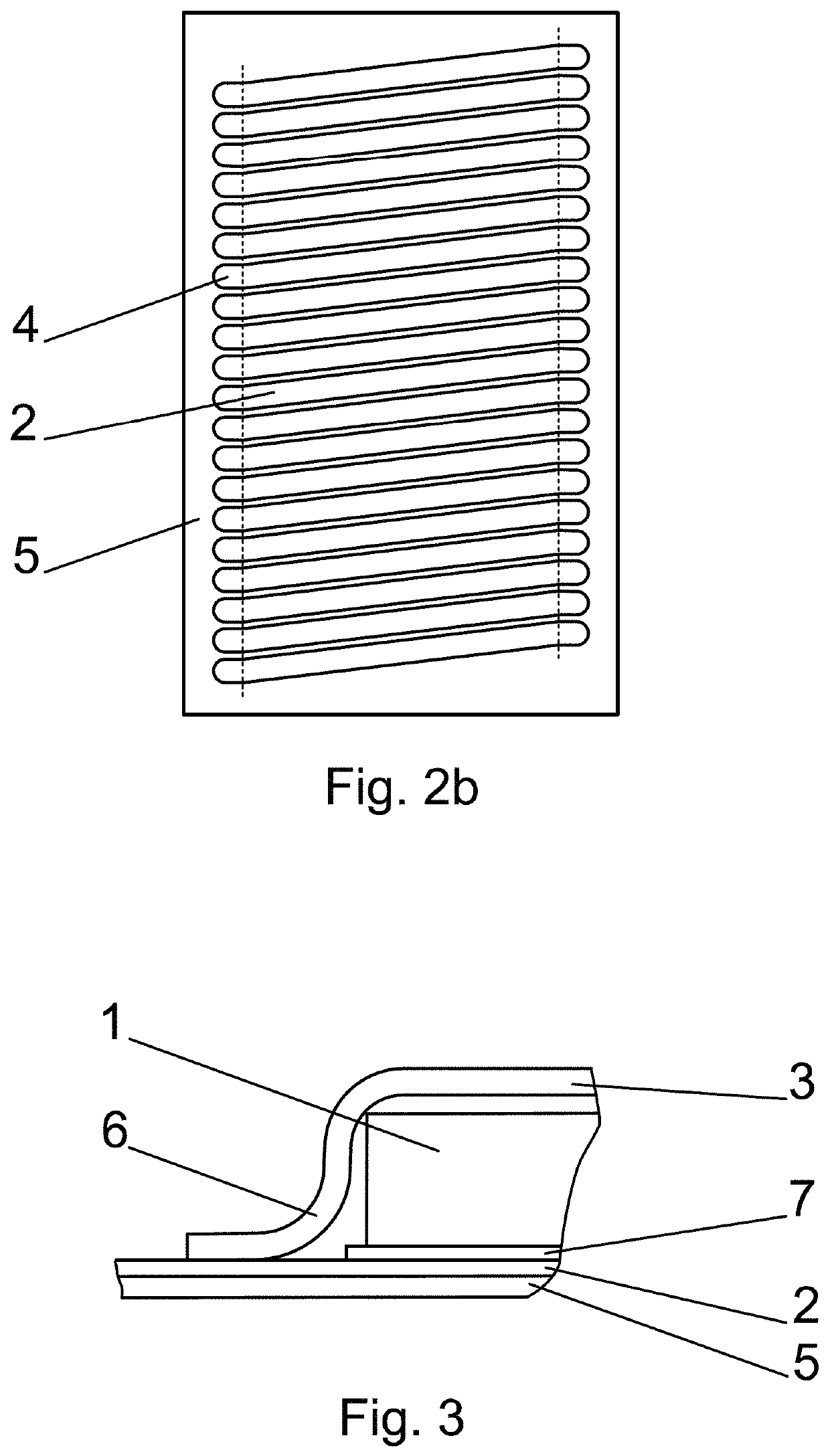
[0056]The substrate 5 is a non-conductive pad on which the layer with a group of conductive strips 2 is pressed. The conductive strips 2 in this example are parallel; the antenna has a constant angle of the pitch of all threads. Each conductive strip 2 is independent; it is not connected within the substrate 5 with the neighboring conductive strip 2.

[0057]The core 1 is placed on the substrate 5 in such a way that it is co-axial with the longitudinal axis of the flat element which is formed by a group of the conductive strips 2. The axis of the core 1 creates and angle of approximately 80° with the conductive strips 2.

[0058]After the placement of the core 1 on the substr...

example 2

[0064]In this example according to FIGS. 1 to 3, 5, 7 and 9 the antenna is produced directly on the PCB of the microSD card. The conductive strips 2 are produced on the PCB. Bonding is used during the mounting of the chips on the PCB; this bonding at the same time produced a connection of the opposite ends of the conductive strips 2 in the same way as in example 1. After gradual creation of all bonding connections of the wires 3, the core 1 is inserted into the created channel between the wires 3 and the conductive strips 2.

[0065]The conductive strips 2 in the example are 0.256 mm wide and from both sides of the core they overhang in length of 0.44 mm. The core 1 has groundplan dimensions 8.9×2.3 mm. The thickness of the core 1 is 0.291 mm.

example 3

[0066]In this example of realization according to FIG. 8 nine wires 3 are used for a connection of a single thread; the wires 3 have circular cross-section and connect the opposing connecting surfaces 4 of two neighboring conductive strips 2. Individual bonds (connecting points) are distributed chequerwise on a connecting surface 4; that is, they are distributed in such a way that the wires 3 can lead above the core 1 tightly close to each other, and at the same time that a small surface suffices for connection.


PUM


Abstract

Part of the conductive loop of the threads is formed by a printed circuit on the substrate (5), where the group of the conductive strips (2) placed side by side is produced, and the core (1) is placed on them. The conductive strips (2) overhang from the groundplan of the core (1) and the ends of the conductive strips (2) overhanging on both sides of the core (1) form the connecting surfaces (4). The wires (3) shaped for the encirclement of the core (1) are connected to the connecting surfaces (4), whereby the wire (3) connects a connecting surface (4) of one conductive strip (2) with the connecting surface (4) on the opposite end of the neighboring conductive strip (2). After bonding to one end of the conductive strip (2) the wire is shaped above the substrate (5) by bending in such a way that it arches over the space intended for the core (1) and all wires (3) are shaped in such a way that they produce a channel for the core (1) placed on the substrate (5). The conductive strips (2) are sloped from the normal of the core (1) under an angle pursuant to the pitch of the thread and the wires (3) are led in the opposite slope under the same angle.

Description

CROSS REFERENCE TO RELATED APPLICATION[0001]This application is a national stage entry of PCT / IB2017 / 055634 filed Sep. 18, 2017, under the International Convention and claiming priority over Slovak application PP 50056-2016 filed Sep. 19, 2016.FIELD OF TECHNOLOGY[0002]The invention concerns thin antenna with a core with small dimensions which is suitable mainly for deposition to the cased carriers such as removable memory cards, SIM cards, mobile communication devices and so on. The antenna achieves excellent emitting characteristics even from the shaded placement and it is suitable for RFID and / or NFC applications. The invention also discloses highly productive method of production of the antenna with the core.PRIOR ART[0003]Mainly flat antennas in shape of conductive loops are used for NFC / RFID, whereby in situation of small dimensions of the carrier for placement of the conductor whole available surface is used. Basic theoretical and academic publications hold a position that in ...

Claims


Application Information

Patent Timeline
Patent Type & Authority Patents(United States)
IPC IPC(8): G06K19/06H01Q1/22H01Q1/38H01Q7/06G06K19/077
CPCH01Q7/06G06K19/07773G06K19/07749H01Q1/2225H01Q1/38
Inventor HUBINAK, EMIL
Owner LOGOMOTION SRO
Why Eureka
Try Eureka