
Method of fabricating transparent Anti-reflective article

a technology of anti-reflection and transparent objects, which is applied in the direction of anti-reflection coatings, photomechanical devices, instruments, etc., can solve the problems of hazy reflection image, reduced light intensity, and difficult viewing of transparent electronic display screens made of glass or plastic, so as to minimize light diffraction and random scattering therethrough, and similar shape and size

Active Publication Date: 2013-09-05
WAYNE STATE UNIV
View PDF3 Cites 0 Cited by
  • Summary
  • Abstract
  • Description
  • Claims
  • Application Information

AI Technical Summary

Benefits of technology

This approach reduces ambient light reflection without image distortion, providing a clear and richly colored view with a wider angle of view, and can be applied to various transparent devices like display screens and solar cells.

Problems solved by technology

Transparent electronic display screens made of glass or plastic, such as cell phone screens, computer screens, and TV monitors including liquid crystal displays (LCD), are difficult to view as external ambient light reflects off their surface.
While this reduces the intensity of light, it does, however, leave a hazy image of the reflection which may block the onscreen image.
However, there are very few transparent coating materials available with a low refractive index for index matching.
Furthermore, it is difficult to find a transparent coating material to match the particular range of most glass and polymers.

Method used


Image

  • Method of fabricating transparent Anti-reflective article
  • Method of fabricating transparent Anti-reflective article
  • Method of fabricating transparent Anti-reflective article

Examples


Embodiment Construction

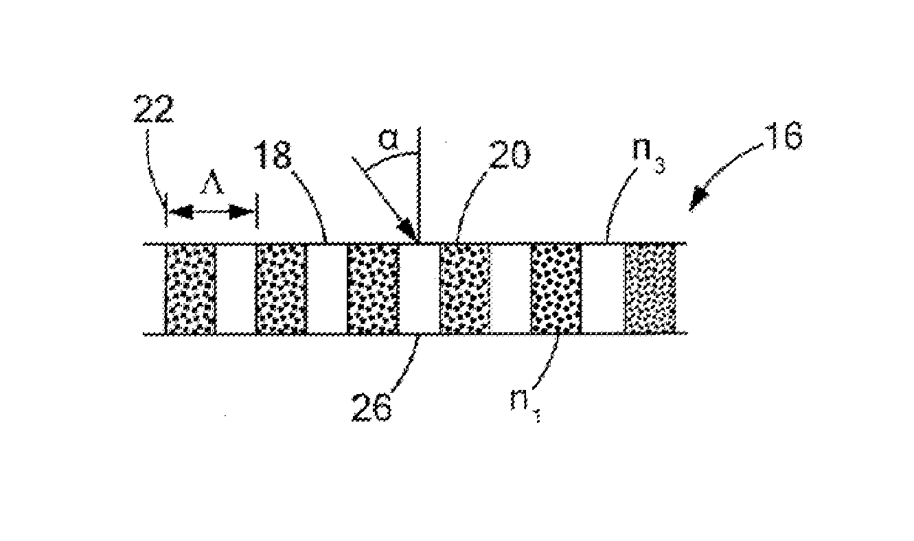
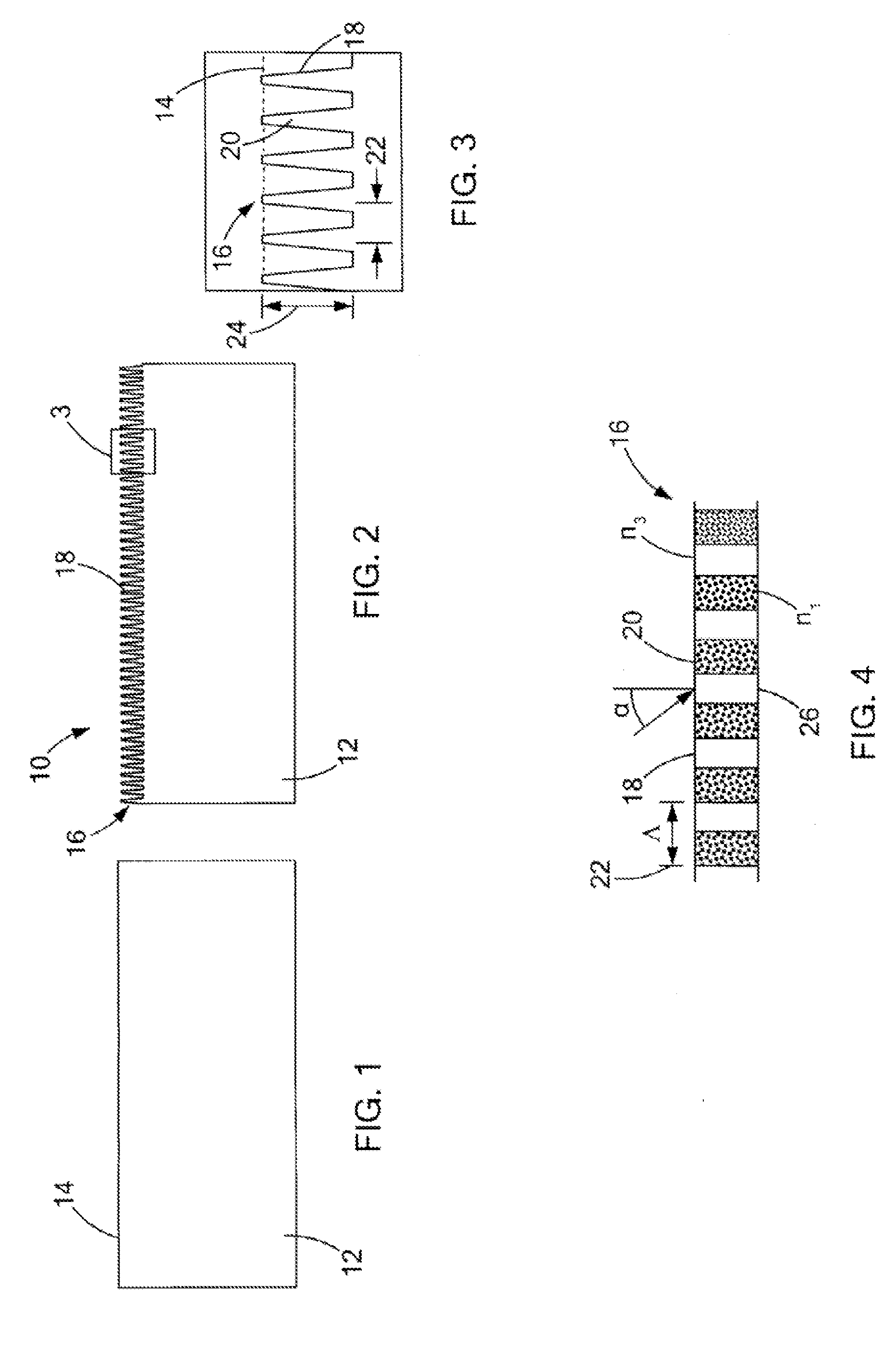
[0016]The present invention generally provides an anti-reflective transparent article. The anti-reflective transparent article may be used in display screens for computer and television monitors, cell phones, cameras, and pocket PCs. The anti-reflective transparent article may also be used in optical sensors and solar cells. In one embodiment, the article comprises a transparent substrate having an anti-reflective layer including a subwavelength nano-structured surface having a plurality of protuberances. The subwavelength nano-structured surface is preferably formed through use of a nanosphere lithography technique. The subwavelength nano-structured surface lowers the refractive index of the transparent substrate and thus reduces the reflection of ambient light.

[0017]FIG. 1 illustrates a transparent substrate 12 having a first surface 14 and a refractive index n1. FIG. 2 illustrates an anti-reflective transparent article 10 in accordance with one embodiment of the present invention...


PUM

PropertyMeasurementUnit
distanceaaaaaaaaaa
distanceaaaaaaaaaa
distanceaaaaaaaaaa

Abstract

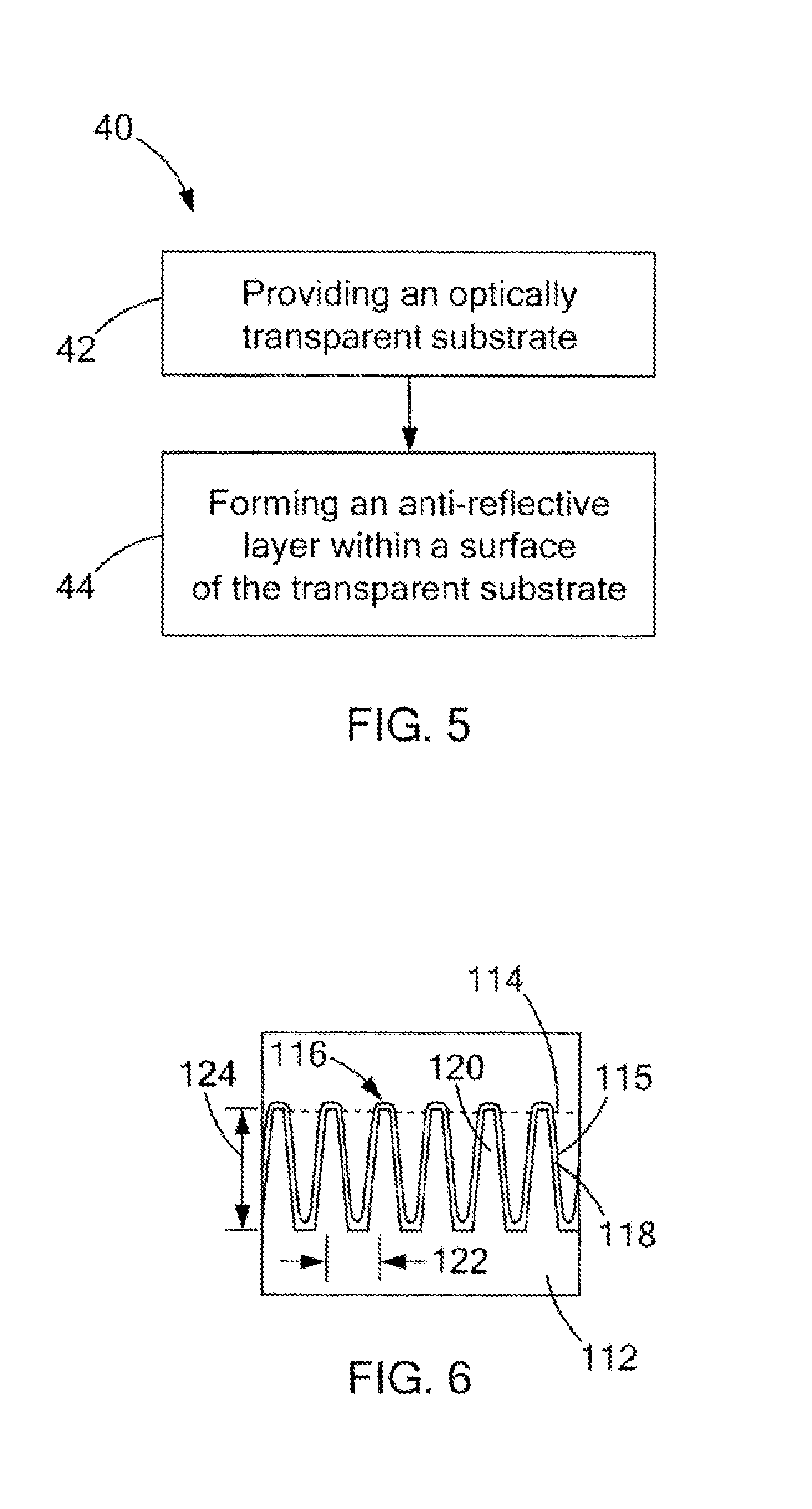
A method of fabricating an anti-reflective optically transparent structure includes the steps of providing an optically transparent substrate having a first refractive index and a first surface; and forming an anti-reflective layer within the first surface of the transparent substrate. The anti-reflective layer is made by forming a nano-scale pattern within the first surface defining a subwavelength nano-structured second surface of the anti-reflective layer including a plurality of protuberances having a predetermined maximum distance between adjacent protuberances and a predetermined height for a given wavelength such that the anti-reflective layer includes a second refractive index lower than the first refractive index to minimize light diffraction and random scattering therethrough. The predetermined height is approximately equal to a quarter of the given wavelength divided by the second refractive index. One of nanosphere lithography, deep ultra-violet photolithography, electron beam lithography, and nano-imprinting may be used to form the anti-reflective layer.

Description

CROSS-REFERENCE TO RELATED APPLICATIONS[0001]This application is a division of U.S. application Ser. No. 12 / 404,863 filed on Mar. 16, 2009, entitled “TRANSPATENT ANTI-REFLECTIVE ARTICLE AND METHOD OF FABRICATING SAME,” which is a continuation-in-part of U.S. application Ser. No. 12 / 050,807 filed on Mar. 18, 2008, entitled “TRANSPARENT HYDROPHOBIC ARTICLE HAVING SELF-CLEANING AND LIQUID REPELLANT FEATURES AND METHOD OF FABRICATING SAME,” which is a continuation of International Application No. PCT / US2006 / 036187 filed on Sep. 15, 2006, entitled “TRANSPARENT HYDROPHOBIC ARTICLE HAVING SELF-CLEANING AND LIQUID REPELLANT FEATURES AND METHOD OF FABRICATING SAME” and claims the benefit of U.S. Provisional Application Ser. No. 60 / 718,587 filed on Sep. 19, 2005, entitled “TRANSPARENT HYDROPHOBIC ARTICLE HAVING SELF-CLEANING AND LIQUID REPELLANT FEATURES AND METHOD OF FABRICATING SAME,” the entire contents of each are incorporated herein by reference.BACKGROUND OF THE INVENTION[0002]The prese...

Claims


Application Information

Patent Timeline
Patent Type & Authority Applications(United States)
IPC IPC(8): C09D5/00
CPCC03C17/28C03C2217/732C09D5/006C03C2217/77C03C2217/76
Inventor ZHAO, YANGWANG, JINSONG
Owner WAYNE STATE UNIV
Learn More