Surface illumination fixture and surface illumination device

a technology of surface illumination and illumination device, which is applied in the direction of semiconductor devices for light sources, fixed installations, lighting and heating apparatus, etc., can solve the problems of increasing weight and production costs, and achieve the effects of low light transmittance, low light reflectance, and high light reflectan

Inactive Publication Date: 2013-02-21
OPTO DESIGN INC
View PDF3 Cites 54 Cited by
  • Summary
  • Abstract
  • Description
  • Claims
  • Application Information

AI Technical Summary

Benefits of technology

[0033]In the surface illumination fixture of the invention, the casing and the light-guide reflection plate are formed by a member having a high light reflectance and a low light transmittance, the light-guide reflection plate is divided into regions corresponding to the point light sources, each region is formed to have a lower light reflectance and a higher light transmittance as the distance from the corresponding point light source increases. Even when a point light source having strong directivity, such as an LED is therefore used as the light source, a surface illumination fixture that uses light from the point light source at high efficiency and can provide uniform illumination light on a face set apart from an emitting surface of the point light source by a predetermined distance while suppressing the generation of glare in a light emitting direction, can be provided at low cost.
[0034]With the surface illumination fixture of the invention, an annular surface illumination fixture in which the casing and the light-guide reflection plate are formed into an annular shape, and that provides the advantageous effects, can be provided.
[0035]With the surface illumination fixture of the invention, a disc-shaped surface illumination fixture in which the casing and the light-guide reflection plate are formed into a disc shape and that provides the advantageous effects, can be provided.
[0036]In the surface illumination fixture of the invention, both the casing and the light-guide reflection plate have a surface coated with a flame-retardant light-transmissive material. In case of fire or other emergency in a building where the surface illumination fixture is installed, the surface illumination fixture is unlikely to be burned, thereby preventing a second disaster.
[0037]In the surface illumination fixture of the invention, a plurality of such annular surface illumination light-source devices can be concentrically disposed. Such a surface illumination fixture can provide the advantageous effects and can change the luminance depending on the purpose, thereby increasing the width of surface illumination.
[0038]With the surface illumination fixture of the invention a larger disc-shaped surface illumination fixture that can provide the advantageous effects and has no blank part of point light sources at the center part can be obtained by the combination of the annular surface illumination fixture and the disc-shaped surface illumination fixture. Furthermore, even a large surface illumination fixture can be lightened because the casing is lightweight.

Problems solved by technology

The light guide plate is, however, required to be provided all over an illumination surface, thereby increasing the weight and the production cost.

Method used


Image

  • Surface illumination fixture and surface illumination device
  • Surface illumination fixture and surface illumination device
  • Surface illumination fixture and surface illumination device

Examples


first embodiment

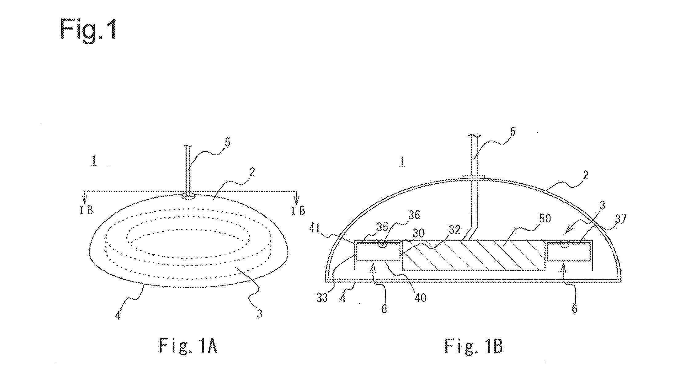
[0062]With reference to FIG. 1, an overview of a surface illumination device of a first embodiment of the invention will be described. FIG. 1A is an exterior view of a pendant surface illumination device for home use as an embodiment of the invention. A surface illumination device 1 includes a surface illumination fixture 3, an illumination cover 2 having an umbrella shape attached to the surface illumination fixture 3 so as to cover the surface illumination fixture 3 from the above, and a diffusion plate 4 closing an opening of the illumination cover 2. The illumination cover 2 has a spherical shape that is partially cut out and is attached with a round-shaped diffusion plate 4 so as to close an opening that is the cut-out part. An adapter (not shown in the drawings) for connecting a power supply and a hanging cord 5 are also attached to the illumination cover 2 for hanging the surface illumination fixture 3 from a ceiling and for supplying electric power to a surface illumination ...

example 1

ALTERNATIVE EXAMPLE 1

[0083]An alternative example 1 of the first embodiment of the invention described above will be described with reference to FIG. 5. In the surface illumination fixture of the alternative example 1, a plurality of annular surface illumination light-source devices 6 having different diameters are concentrically disposed. The annular surface illumination light-source device 6 in the drawing is shown by the layout of the casings. In other words, in the example, the surface illumination device 1 includes two annular surface illumination light-source devices 6A and 6B in a double annular pattern. Such a structure can enlarge the area of the surface illumination device. The outside annular surface illumination light-source device 6A is divided into sixteen segments 313 to 328 and each segment includes one point light source 36a. The inside annular surface illumination light-source device 6B is divided into eight segments and each of the segments 329 to 336 includes one...

second embodiment

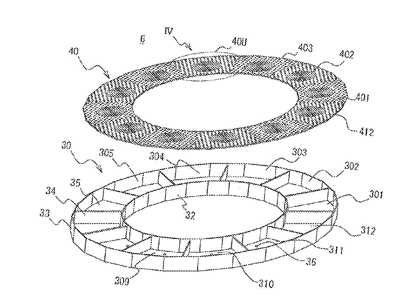
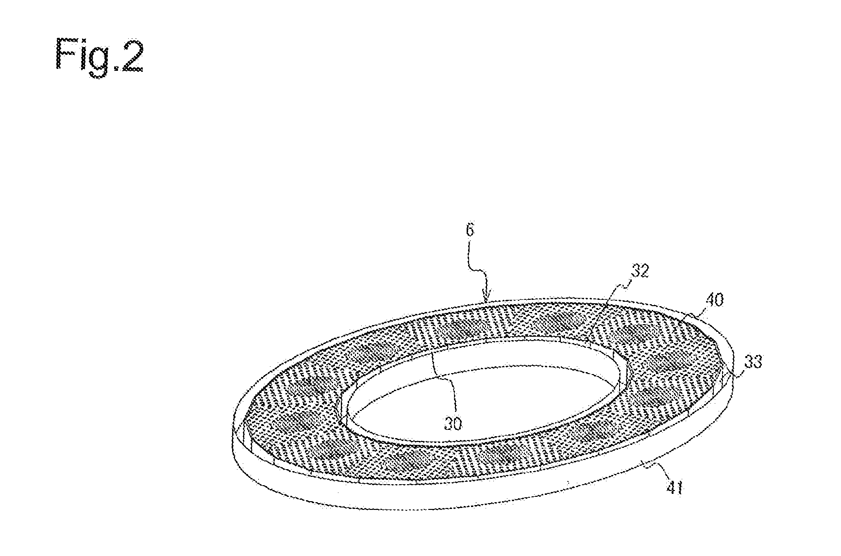
[0092]According to a second embodiment of the invention, in a surface illumination fixture 3, a surface illumination light-source device 6 includes a round casing 30c formed so as to have a round outer shell and a round light-guide reflection plate 40c. A surface illumination light-source device 6C in the second embodiment of the invention will be described hereinafter with reference to FIG. 7 and FIG. 8. FIG. 7 is an exterior perspective view of a surface illumination light-source device 6C used for a surface illumination device 1 in the second embodiment and FIG. 8 is an exploded perspective view of the surface illumination light-source device 6C. In the description below, the points overlapping with the first embodiment will be simplified.

[0093]The surface illumination device 1 of the second embodiment includes a round surface illumination light-source device 6C for converting light from the point light source 36 having strong directivity into surface illumination and an illumina...


PUM

PropertyMeasurementUnit
heightaaaaaaaaaa
light reflectanceaaaaaaaaaa
light transmittanceaaaaaaaaaa

Abstract

[Purpose] To provide a surface illumination fixture using a point light source having strong directivity.
[Constitution] In the surface illumination fixture 3 including a surface illumination light-source device 6 converting light from a plurality of point light sources 36 having strong directivity into surface illumination and an illumination fixture main body 41, the surface illumination light-source device 6 includes a casing 30 having a flat plate part 35 being used to attach the surface illumination light-source device to the illumination fixture main body, lateral plate parts standing from the flat plate part, and an opening on a surface opposite to the flat plate part, and includes a light-guide reflection plate covering the opening. The flat plate part 35, the lateral plate parts 32 and 33, and the light-guide reflection plate 40 are formed by members having a high light reflectance and a low light transmittance. The light-guide reflection plate 40 is formed to have a lower light reflectance and a higher light transmittance as the distance from the corresponding point light source increases. The illumination fixture main body 41 having attaching means for attachment to a ceiling or a wall.

Description

TECHNICAL FIELD[0001]The present invention relates to a surface illumination fixture using a point light source having strong directivity and a surface illumination device using the fixture.BACKGROUND ART[0002]In recent years, point light sources such as light emitting diodes (LED) and laser diodes have been used as light sources for various display devices, illumination devices, and others in place of incandescent bulbs and fluorescent tubes because such point light sources consume less electricity, generate less heat, and have longer service life.[0003]There are various illumination devices using a point light source. Examples of such illumination devices include square and round illumination devices that are attached to a ceiling or a wall in a building to be used for, for example, room illumination, a miniature bulb-type illumination device used as, for example, an outdoor lamp, and a linear illumination device similar to a fluorescent lamp. Recently, LED illumination devices ha...

Claims


Application Information

Patent Timeline
Patent Type & Authority Applications(United States)
IPC IPC(8): F21V7/04
CPCF21S8/061F21V11/14F21Y2103/022F21Y2101/02F21Y2103/33F21Y2115/10F21V14/04F21Y2101/00F21V7/28
Inventor SATO, EIICHISATO, HIROYASUSATO, RIHITO
Owner OPTO DESIGN INC
Why Eureka
Try Eureka