Nuclear reactor refueling methods and apparatuses

Inactive Publication Date: 2013-02-21
BWXT MPOWER INC
View PDF10 Cites 12 Cited by
  • Summary
  • Abstract
  • Description
  • Claims
  • Application Information

AI Technical Summary

Benefits of technology

[0012]In another aspect of the disclosure, an apparatus comprises: a nuclear fuel assembly including mating features at a top of the nuclear fuel assembly; a control rod assembly (CRA) inserted in the nuclear fuel assembly with an upper end of the CRA extending out of the top of the nuclear fuel assembly; and a lifting tool including an upper end configured for attachment with a crane and a plurality of downwardly extending elements surrounding an open central

Problems solved by technology

These refueling approaches ha

Method used


Image

  • Nuclear reactor refueling methods and apparatuses
  • Nuclear reactor refueling methods and apparatuses
  • Nuclear reactor refueling methods and apparatuses

Examples


Embodiment Construction

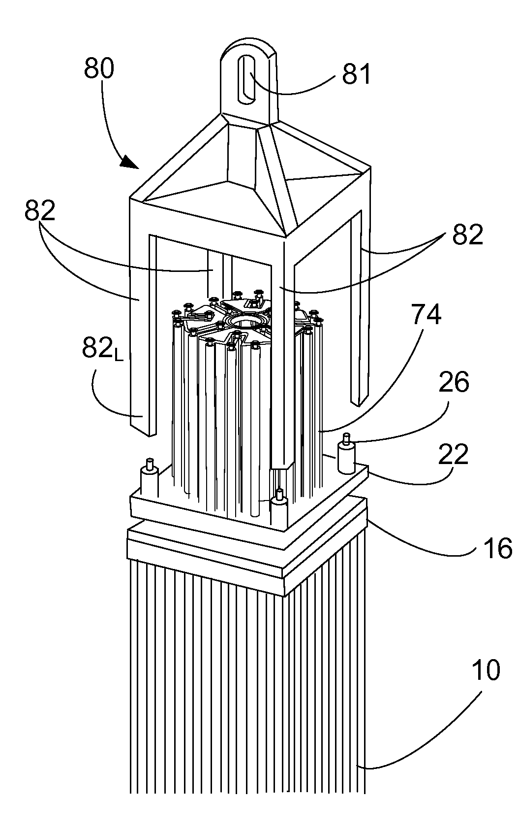
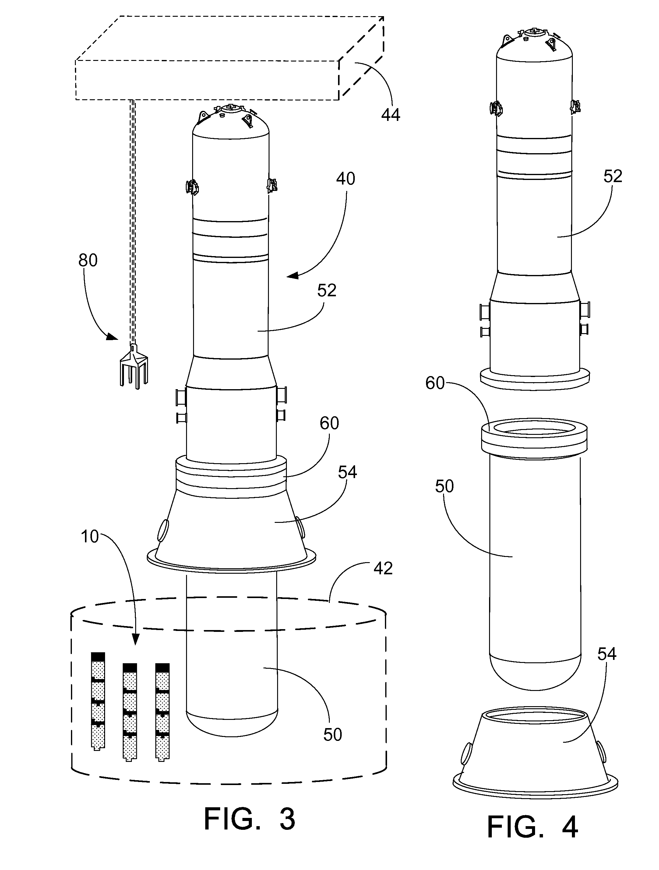
[0026]With reference to FIGS. 3-5, an illustrative nuclear reactor is shown. FIG. 3 shows the nuclear reactor 40 in conjunction with a diagrammatically indicated spent fuel pool 42 and a diagrammatically indicated crane 44. FIG. 4 shows an exploded view of the pressure vessel of the nuclear reactor of FIG. 3. The pressure vessel includes a lower vessel portion 50, an upper vessel portion 52, and a skirt or support structure 54. In the illustrative arrangement, the pressure vessel is mounted vertically (as shown) with at least part of the lower vessel portion 50 disposed below ground level. The bottom of the skirt or support structure 54 is at ground level and supports the pressure vessel and / or biases the pressure vessel against tipping. In the illustrative example of FIG. 3, the spent fuel pool 42 is a below-ground pool containing water and optional additives such as, by way of illustrative example, boric acid (a soluble neutron poison). FIG. 5 shows an exploded perspective view of...


PUM


Abstract

Refueling of a nuclear reactor (40) includes removing a fuel assembly (10). The removal method includes lowering a lifting tool (80) of a crane (44) onto a top of the fuel assembly. The lowered lifting tool including a plurality of downwardly extending elements (82) that surround and vertically overlap a portion (74) of a control rod assembly (70) extending above the top of the fuel assembly. The downwardly extending elements are locked with corresponding mating features (26) at the top of the fuel assembly to connect the lifting tool with the fuel assembly. The connected fuel assembly is moved into a spent fuel pool (42) using the crane, and the lifting tool is disconnected from the top of the fuel assembly by unlocking the downwardly extending elements from the corresponding mating features at the top of the fuel assembly.

Description

BACKGROUND[0001]The following relates to the nuclear reactor arts, electrical power generation arts, nuclear reactor control arts, nuclear electrical power generation control arts, and related arts.[0002]Nuclear reactors employ a reactor core comprising a critical mass of fissile material, such as a material containing uranium oxide (UO2) that is enriched in the fissile 235U isotope. The fuel rod may take various structural configurations, for example including fissile material as pellets embedded in a ceramic matrix or so forth. To promote safety, it is conventional to assemble the core as rods containing the fissile material. A set of rods is preassembled to form a fuel assembly. Preferably, the mass of fissile material in the fuel assembly remains below critical mass. The fuel assemblies are shipped to the reactor site, and are installed in a grid in the reactor pressure vessel to form the reactor core. To prevent a premature chain reaction, suitable neutron absorbing material is...

Claims


Application Information

Patent Timeline
IPC IPC(8): G21C19/10
CPCG21C19/205G21C19/10Y02E30/30
Inventor WALTON, LEWIS A.ALES, MATHEW W.
Owner BWXT MPOWER INC
Why Eureka
Try Eureka