Building Structure

a technology for building structures and concrete, applied in the direction of building components, building parts, building shape, etc., can solve the problems of high labor intensity, potential danger to workers, inherent dimensional and structural irregularities of natural products,

Inactive Publication Date: 2013-02-28
EKCO PATENT & HLDG
View PDF15 Cites 10 Cited by
  • Summary
  • Abstract
  • Description
  • Claims
  • Application Information

AI Technical Summary

Benefits of technology

[0206]It will be appreciated that the various aspects of the invention allow for the pre-fabrication of various components in an industrial manufacturing environment which may present significant advantages. For example safety can be improved since less on-site work needs to be performed. In particular much of the working at height or overhead is eliminated. Cost could also be lowered since automation techniques can be employed during manufacture, delays due to wet weather on site are reduced and speed of installation on site is increased. The placement of installed elements is simplified since placement of reinforcing, ducting and services can either be performed by machine, or if performed by hand these can be performed by a worker at ground level, at a comfortable working height and safe manner.

Problems solved by technology

Current methods of providing concrete formwork are very labour intensive and potentially dangerous for workers.
The use of timber for formwork has certain disadvantages, e.g. timber formwork is only able to be re-used a very limited number of times, it also has the inherent dimensional and structural irregularities associated with a natural product.
Moreover, because the formwork is manually installed on-site, tolerances for installation are relatively loose.
Such installation is very time consuming and potentially hazardous, particularly when the workers are installing timber panels on the bottom of the formwork section for horizontally extending structures like floors or beams onto the support beams.
The placement of each of these additional elements is performed onsite after the formation of the formwork, with each additional job becoming progressively more difficult and hazardous for workers as the working area becomes more cluttered with other elements.
This is also time consuming and potentially dangerous.
One way of ameliorating the complexity, cost and risk of using formwork as described above is to precast the concrete elements off site, but this is only viable in certain situations.

Method used


Image

  • Building Structure
  • Building Structure
  • Building Structure

Examples


Embodiment Construction

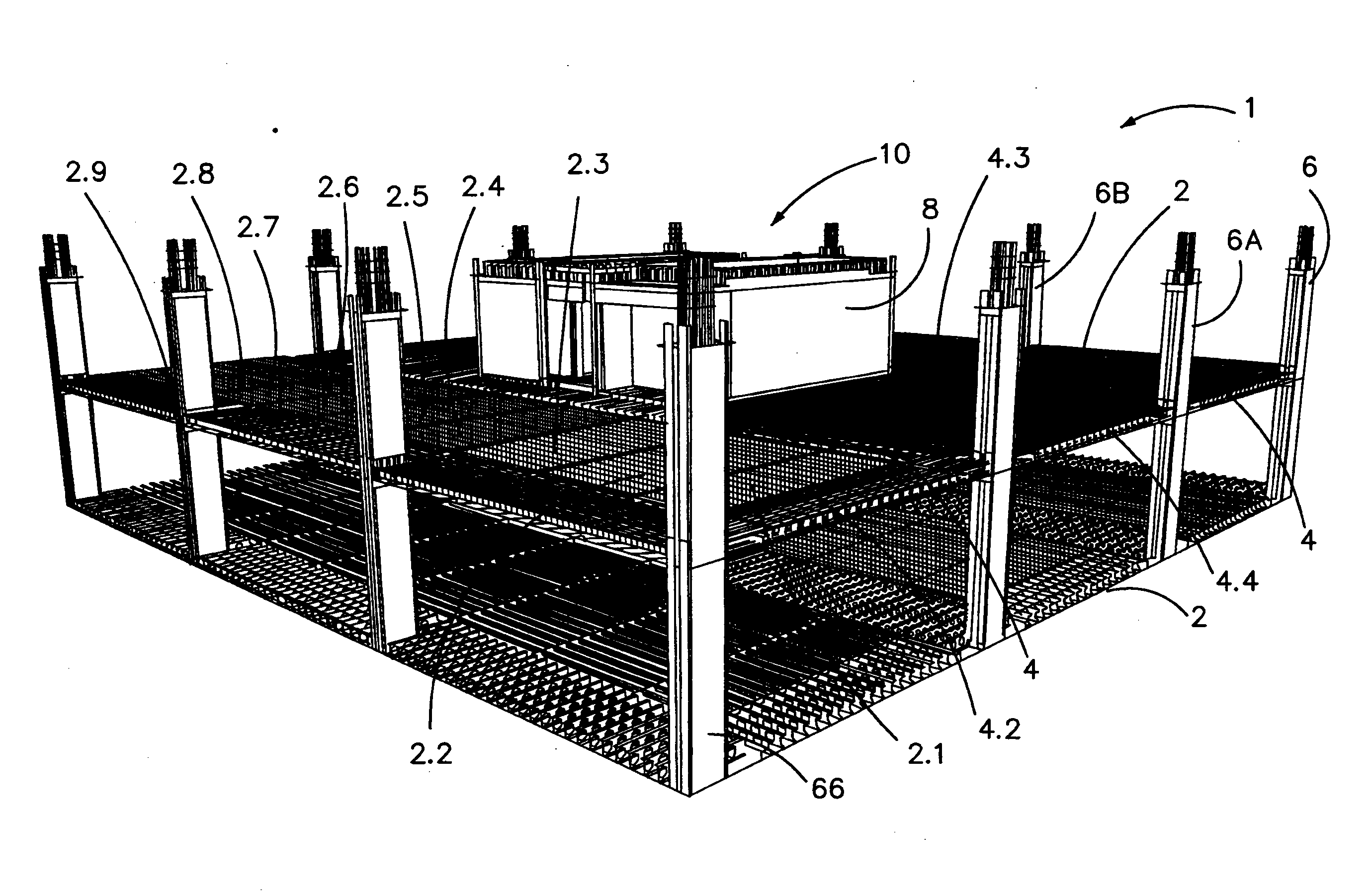
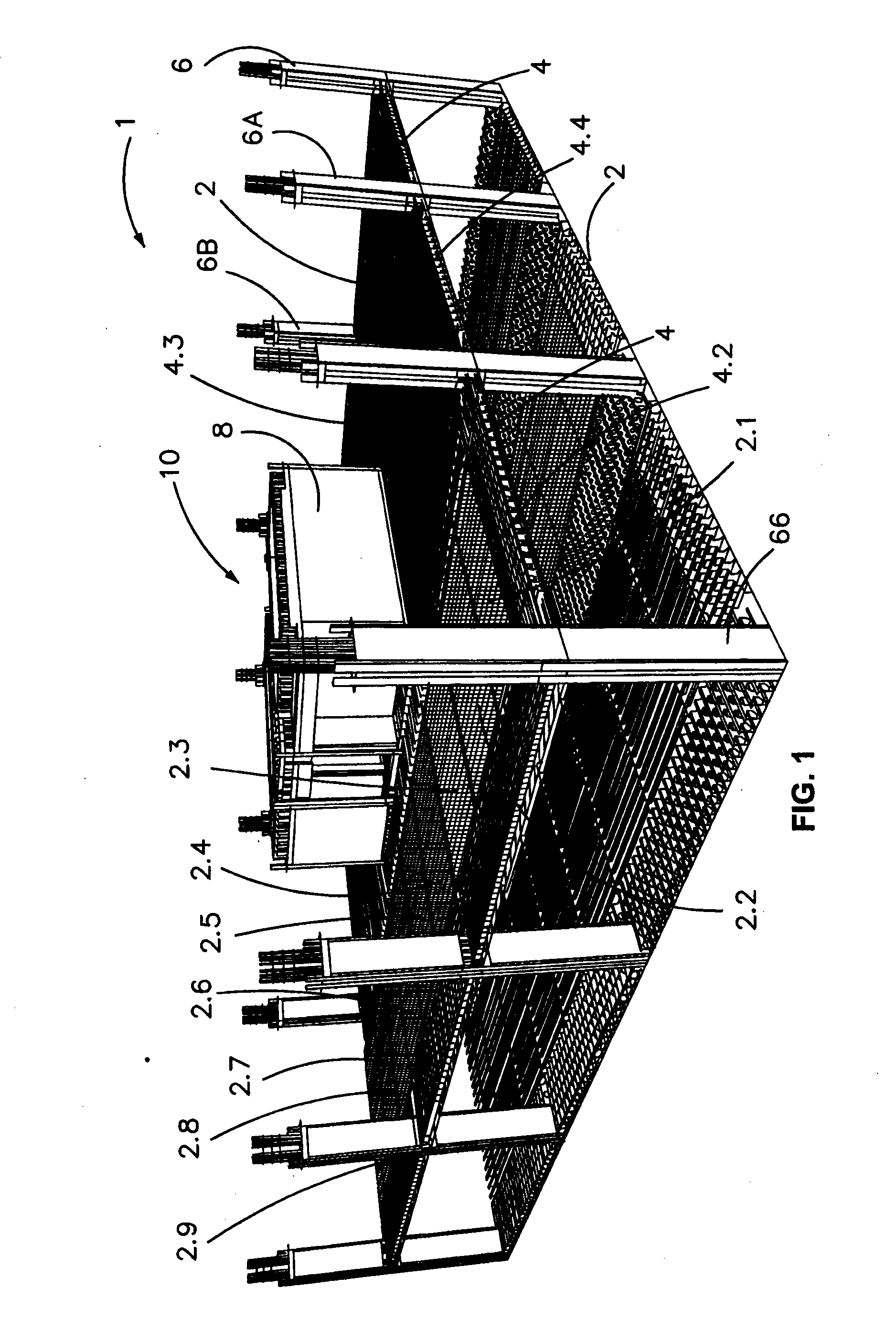
[0117]FIG. 1 shows a partially constructed building 1. The building will ultimately include several storeys, but in FIG. 1 only two are shown. In FIG. 1 the structure of the partial building 1 consists of a plurality of pre-fabricated modules assembled to define an external formwork structure carrying concrete reinforcing bars to strengthen the concrete once it is poured. In FIG. 1 the concrete is not shown. The structure of the building illustrated in FIG. 1 is assembled on site, on suitable foundations (that may be constructed using a similar methodology to the upper storeys illustrated or conventionally) from a plurality of pre-fabricated formwork modules as described below.

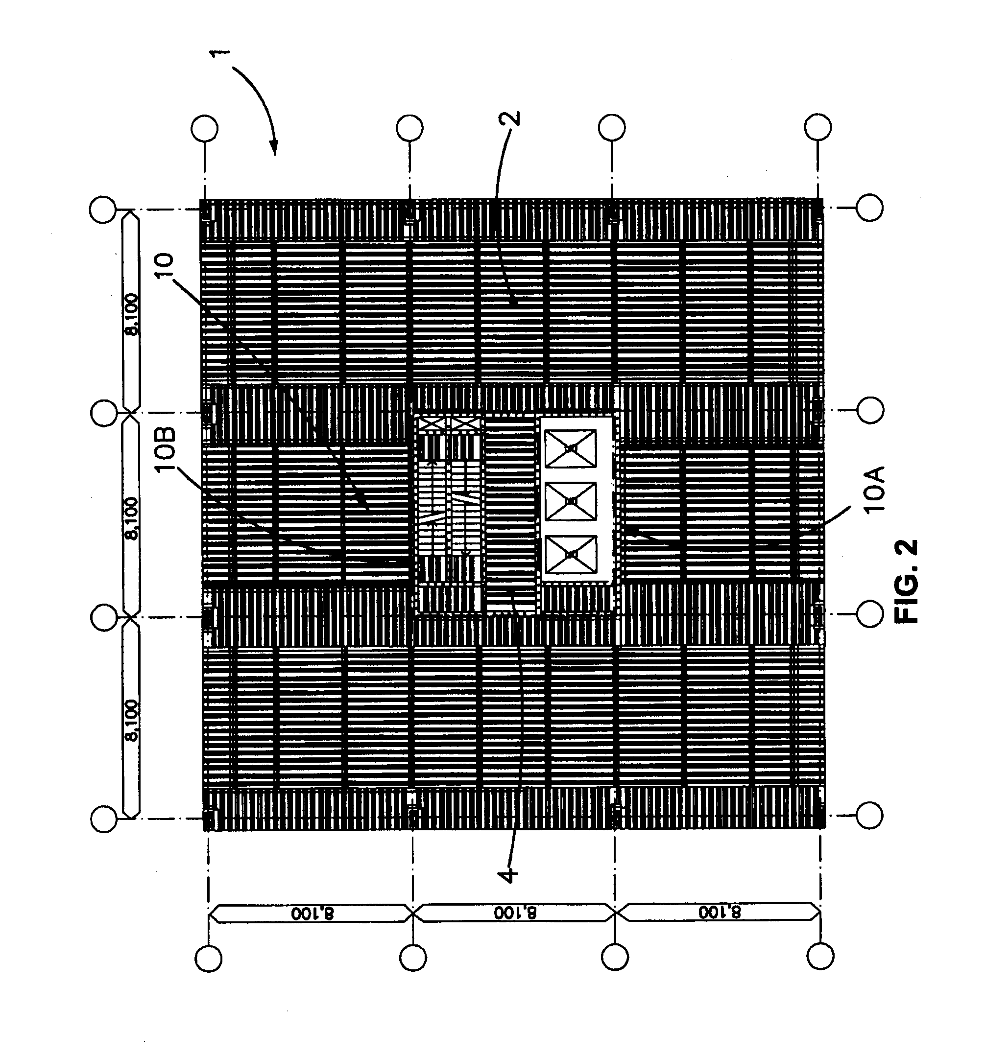
[0118]The building 1 includes various building portions including floors 2, beams 4, columns 6, walls 8 and a central core 10. As shown in FIG. 2 the core 10 is made up of two core portions 10A and 10B.

[0119]As will be described, the floor portions 2 and beam portions 4 have a similar construction. As best ill...


PUM


Abstract

The present invention relates to the construction of buildings as well as elements, structures and methods used in their construction. There is described a pre-fabricated formwork module (12) for a building portion. The module 12 includes two or more panels (14) each including a boundary portion (18) and one or more projecting structures (16). In the module (12) the panels are arranged such that their boundary portions (18) together define a first substantially continuous boundary for forming concrete and the projecting structures (18) project from the boundary into the concrete. The module (12) also include one or more reinforcing bars (30A) fixed, e.g. fixed to the projecting structures, in position relative to the boundary for transport and to reinforce the concrete.

Description

FIELD OF THE INVENTION[0001]The present invention relates to the construction of concrete buildings as well as elements, structures and methods used in their construction. The invention will be described in relation to the construction of high rise buildings. However, single storey and low rise buildings can also be constructed using aspects of the present invention.BACKGROUND OF THE INVENTION[0002]Buildings having concrete elements are constructed using formwork to create a temporary or permanent cast into which the concrete to form the structure of the building is poured. Temporary formwork is removed after curing of the concrete, whilst permanent formwork remains as part of the structure of the building after the concrete has cured. Current methods of providing concrete formwork are very labour intensive and potentially dangerous for workers.[0003]Traditionally, timber formwork has been used. Timber formwork is built on site by a carpenter who uses timber to create a mould into w...

Claims


Application Information

Patent Timeline
Patent Type & Authority Applications(United States)
IPC IPC(8): E04B1/16E04G11/06E04G11/02E04G11/36E04B2/86E04B2/84
CPCE04B1/161E04B1/165E04B2002/867E04B2/8635E04B5/40E04B2/8623E04B1/16E04B1/348E04B2/86E04G11/36
Inventor KATSALIDIS, EPAMINONDAS
Owner EKCO PATENT & HLDG
Why Eureka
Try Eureka