Foam-in-bag device with bag-status indicator

a technology of a bag and a status indicator, which is applied in the direction of rod-shaped objects, decorative covers, packaging, etc., can solve the problems of insufficient sealing of the bag and/or the subsequent bag, inability to properly seal the bag, and inability to fully cut the bag when the bag is pulled

Active Publication Date: 2013-02-28
PREGIS INTELLIPACK CORP
View PDF46 Cites 19 Cited by
  • Summary
  • Abstract
  • Description
  • Claims
  • Application Information

AI Technical Summary

Benefits of technology

[0006]In one embodiment, disclosed herein is a foam-in-bag dispensing system, including a dispensing apparatus operative to dispense foam precursor, the foam precursor being configured for expanding and solidifying into a polymeric foam, to a dispensing location between first ...

Problems solved by technology

One particular problem with existing foam-in-bag dispensing apparatus is that, during use, the operator thereof may be prone to remove the bag from the apparatus too early.
If a bag is pulled to early, the bag and/or the subsequent bag being filled, may not be prop...

Method used


Image

  • Foam-in-bag device with bag-status indicator
  • Foam-in-bag device with bag-status indicator
  • Foam-in-bag device with bag-status indicator

Examples


Embodiment Construction

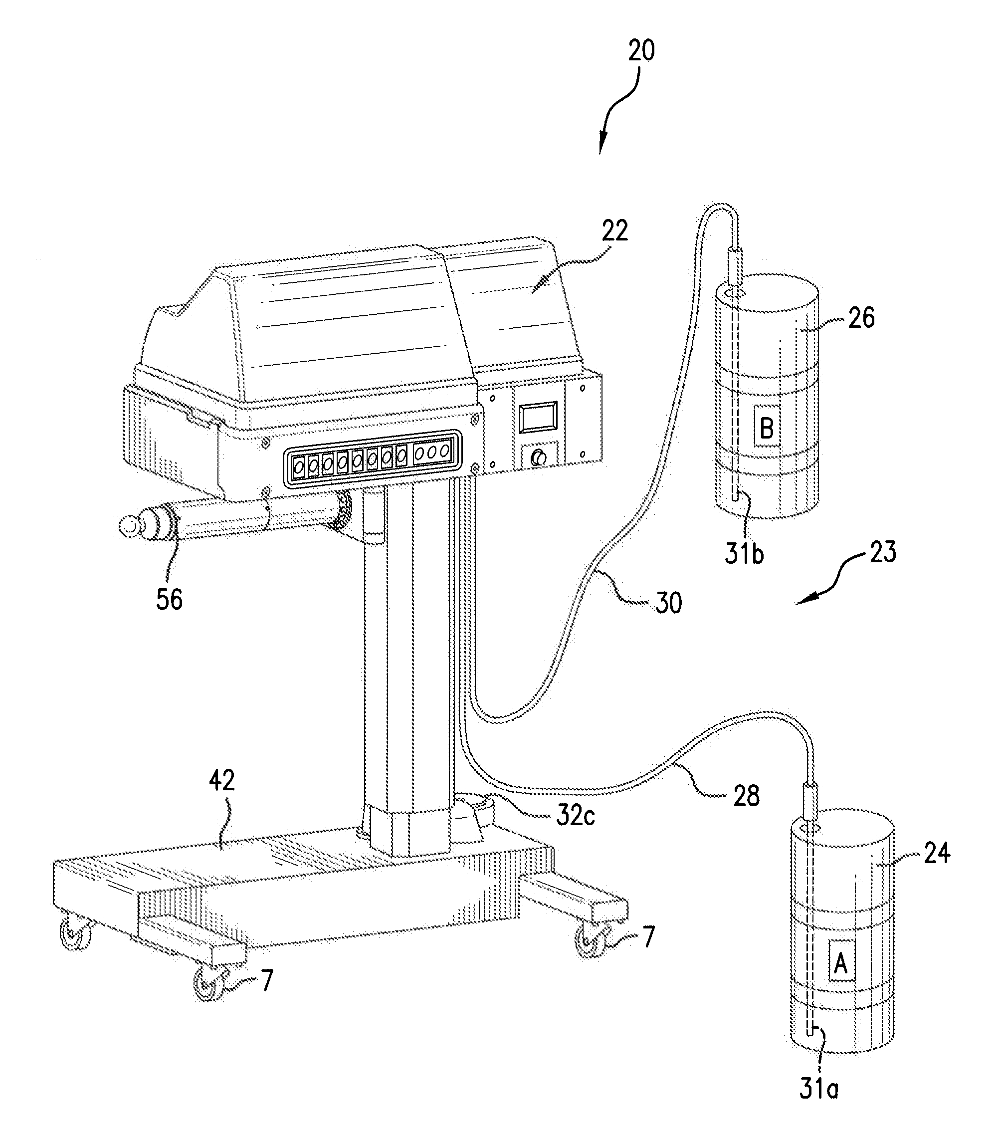
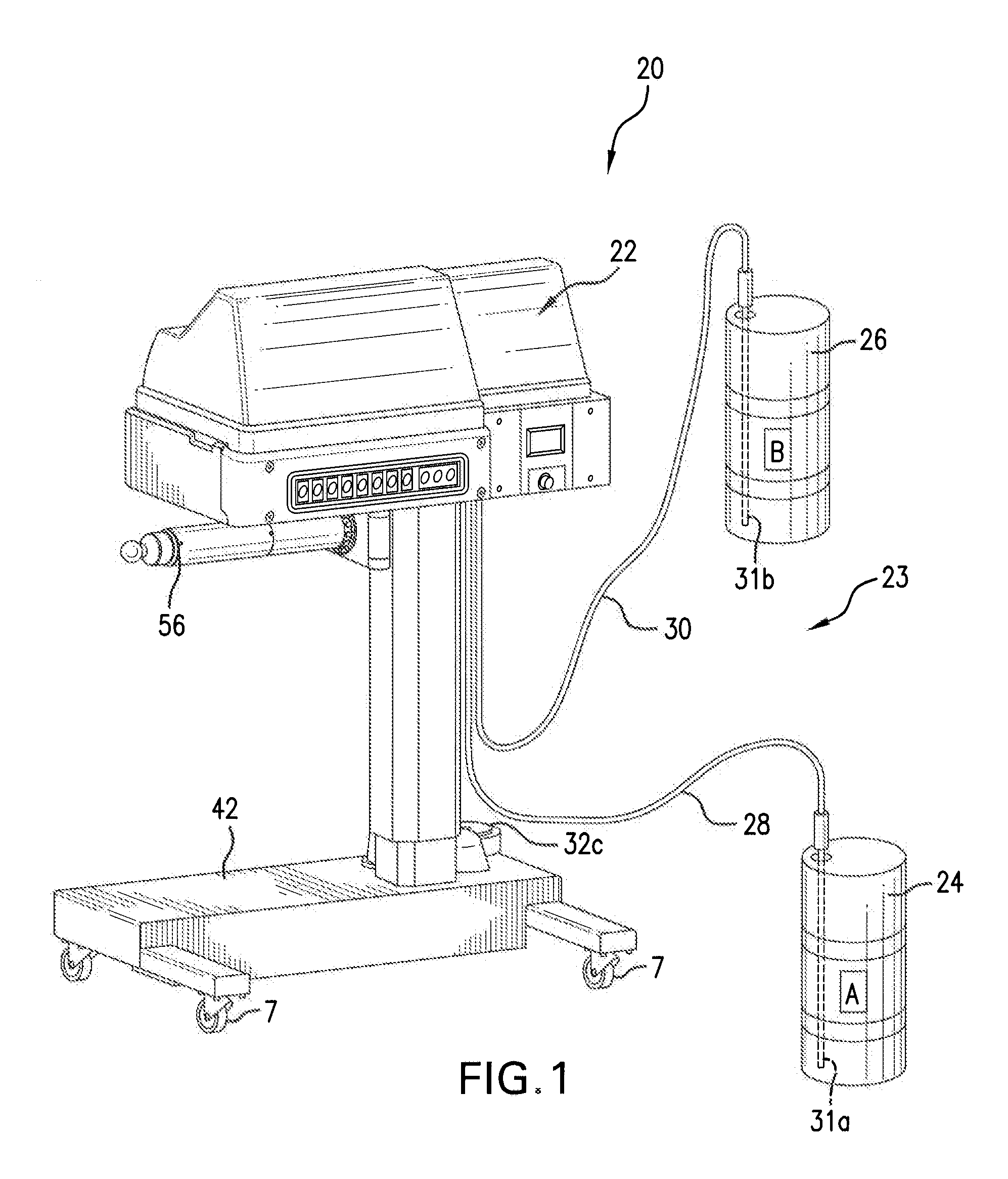
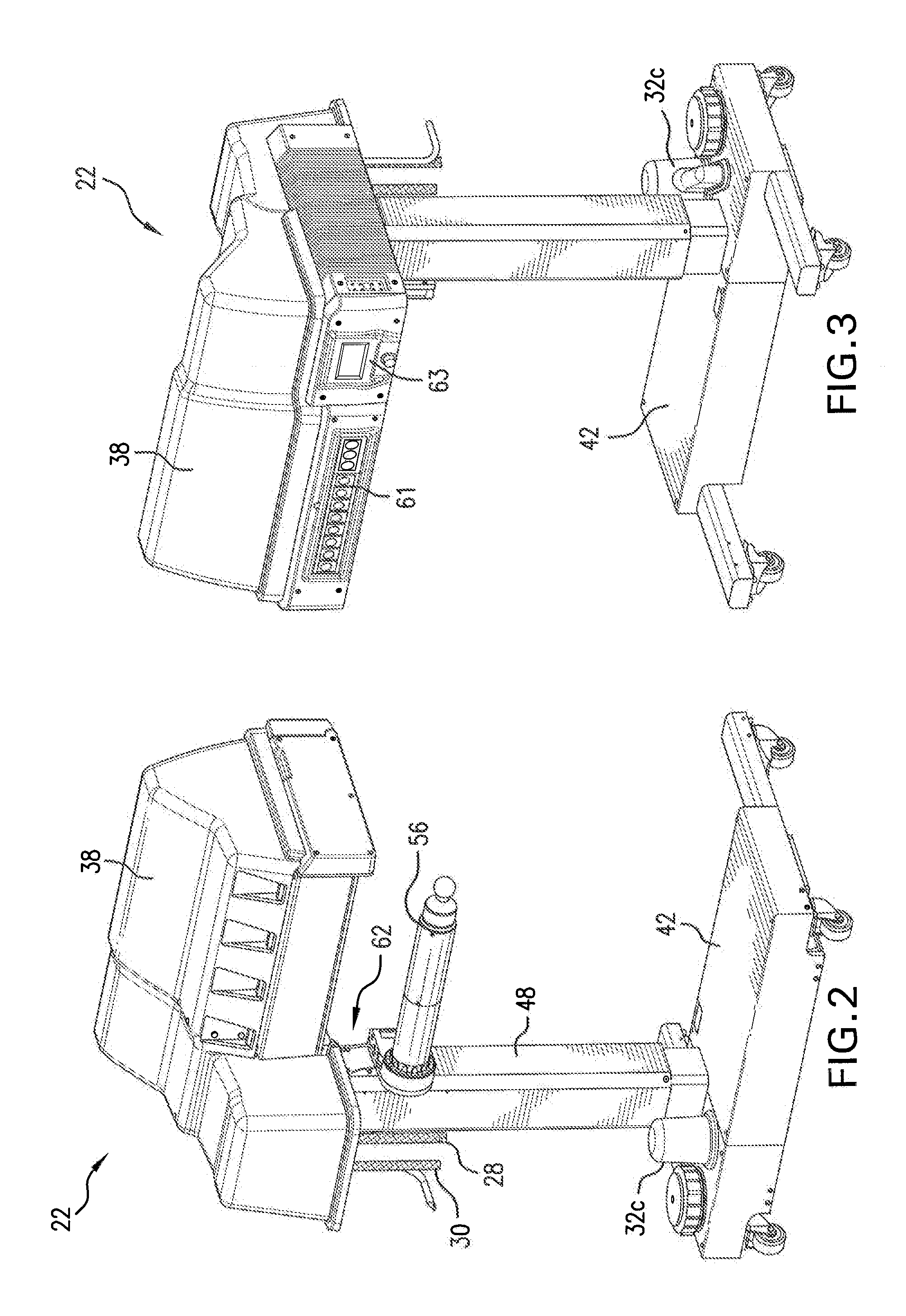
[0025]With general reference to FIGS. 1-4, the present disclosure is directed to a dispensing system and components therefore. In particular, the present disclosure a foam-in-bag dispensing apparatus 20 used to produce foam-filled bags, and components having application in the foam-in-bag apparatus. Specific aspects of the apparatus 20 are discussed as follows.

[0026]FIG. 1 illustrates a preferred embodiment of the dispensing system 20 of the present disclosure, which includes dispenser system 22 in communication with the chemical supply system 23, itself including chemical supply container 24 (supplying chemical component A) and chemical supply container 26 (supplying chemical component B). Chemical hoses 28 (chemical A) and 30 (chemical B), in connection with tubes 31a, 31b (extending into the containers 24,26), provide fluid communication between respective chemical supply containers 24, 26 and in-line pumps 32a, 32b mounted on dispenser system 22 (see FIG. 11). Dispenser system 2...


PUM


Abstract

Disclosed herein is a foam-in-bag dispensing system, including a dispensing apparatus operative to dispense foam precursor, the foam precursor being configured for expanding and solidifying into a polymeric foam, to a dispensing location between first and second web plies extending respectively on first and second sides of the dispensing apparatus; and a bag-status indicator associated for providing an indication to the operator indicative of the readiness of the bag for removal from the device for avoiding premature bag removal.

Description

TECHNICAL FIELD [0001]The present disclosure is directed to a dispensing system and components therefore. In particular, the present disclosure is directed to a foam-in-bag dispensing apparatus used to produce foam-filled bags, and components having application in the foam-in-bag apparatus.BACKGROUND [0002]Foam material dispensers have been developed including those directed at dispensing polyurethane foam precursor that are mixed together to form a polymeric product. The chemicals are often selected so that they harden following a generation of carbon dioxide and water vapor, and they have been used to form “hardened” (e.g., a cushioning quality in a proper fully expanded state) polymer foams in which the mechanical foaming action is caused by the gaseous carbon dioxide and water vapor leaving the mixture.[0003]In particular techniques, synthetic foams such as polyurethane foam are formed from liquid organic resins and polyisocyanates in a mixing chamber (e.g., a liquid form of iso...

Claims


Application Information

Patent Timeline
IPC IPC(8): B65B61/28B23Q15/24B65B61/06B65B57/00B65B57/18
CPCB29C44/182B29K2275/00B29C44/60B29L2031/7128B29L2031/7138B31D5/0078Y10T83/0467Y10T83/152B65B51/146B65B57/00B65B57/02B65B57/08B65B57/18B65B61/04
Inventor JONES, MICHAEL PAUL
Owner PREGIS INTELLIPACK CORP
Why Eureka
Try Eureka