Riding type mower

a mower and pedal pivot technology, applied in the direction of alternative steering control, braking system, transportation and packaging, etc., can solve the problem that the operation portions of the left and right rear wheel brakes tend to be long, and the coupling rod connecting the pedal pivot with the operation portion of the left and right rear wheel brakes is long. , to achieve the effect of simple structure, short length and simple configuration

Active Publication Date: 2013-02-28
KUBOTA LTD
View PDF2 Cites 15 Cited by
  • Summary
  • Abstract
  • Description
  • Claims
  • Application Information

AI Technical Summary

Benefits of technology

[0008]An advantage of the present invention is to provide a riding type mower that is capable of controlling a left-right pair of rear wheel brakes by controlling a brake pedal in a driver section while having a simple configuration.
[0009]One aspect of the present invention is related to a riding type mower including a self-propelled vehicle and a mowing apparatus. The self-propelled vehicle includes a driver step provided to a front portion of the vehicle body, an engine provided to a rear portion of the vehicle body, a left-right pair of rear wheel drive apparatuses provided on a front side of the vehicle body with respect to the engine and on a rear side of the vehicle body with respect to the driver step and transmitting drive force from the engine to each of a left-right pair of rear wheels, and a left-right pair of rear wheel brakes separately provided to the left-right pair of rear wheel drive apparatuses. The mowing apparatus is raisably and lowerably provided on the front side of the vehicle body with respect to the left-right pair of rear wheel drive apparatuses below the driver step. The riding type mower includes a coupling mechanism coupling a brake pedal provided to the driver step with operation portions of the left-right pair of rear wheel brakes. The coupling mechanism includes: a relay shaft; a pedal coupling rod; a left brake coupling rod; and a right brake coupling rod, the relay shaft being rotatably provided in a lateral direction of the vehicle on the rear side of the vehicle body with respect to the mowing apparatus and on the front side of the vehicle body with respect to the left-right pair of rear wheel drive apparatuses, the pedal coupling rod extending in the front-rear direction of the vehicle body above the mowing apparatus and connecting to the brake pedal and to the relay shaft, the left brake coupling rod extending in the front-back direction of the vehicle body and connecting to a left end of the relay shaft and to the operation portion of the left rear wheel brake, and the right brake coupling rod extending in the front-back direction of the vehicle body and connecting to a right end of the relay shaft and the operation portion of the right rear wheel brake.
[0010]According to the configuration of the present invention, operation force of the brake pedal is transmitted to the relay shaft by the pedal coupling rod, the relay shaft being provided on the rear side of the vehicle body with respect to the mowing apparatus and on the front side of the vehicle body with respect to the left-right pair of rear wheel drive apparatuses. The operation f

Problems solved by technology

Thus, the coupling rods connecting the pedal pivot with the operati

Method used


Image

  • Riding type mower
  • Riding type mower
  • Riding type mower

Examples


Embodiment Construction

[0035]The particulars shown herein are by way of example and for purposes of illustrative discussion of the embodiments of the present invention only and are presented in the cause of providing what is believed to be the most useful and readily understood description of the principles and conceptual aspects of the present invention. In this regard, no attempt is made to show structural details of the present invention in more detail than is necessary for the fundamental understanding of the present invention, the description is taken with the drawings making apparent to those skilled in the art how the forms of the present invention may be embodied in practice.

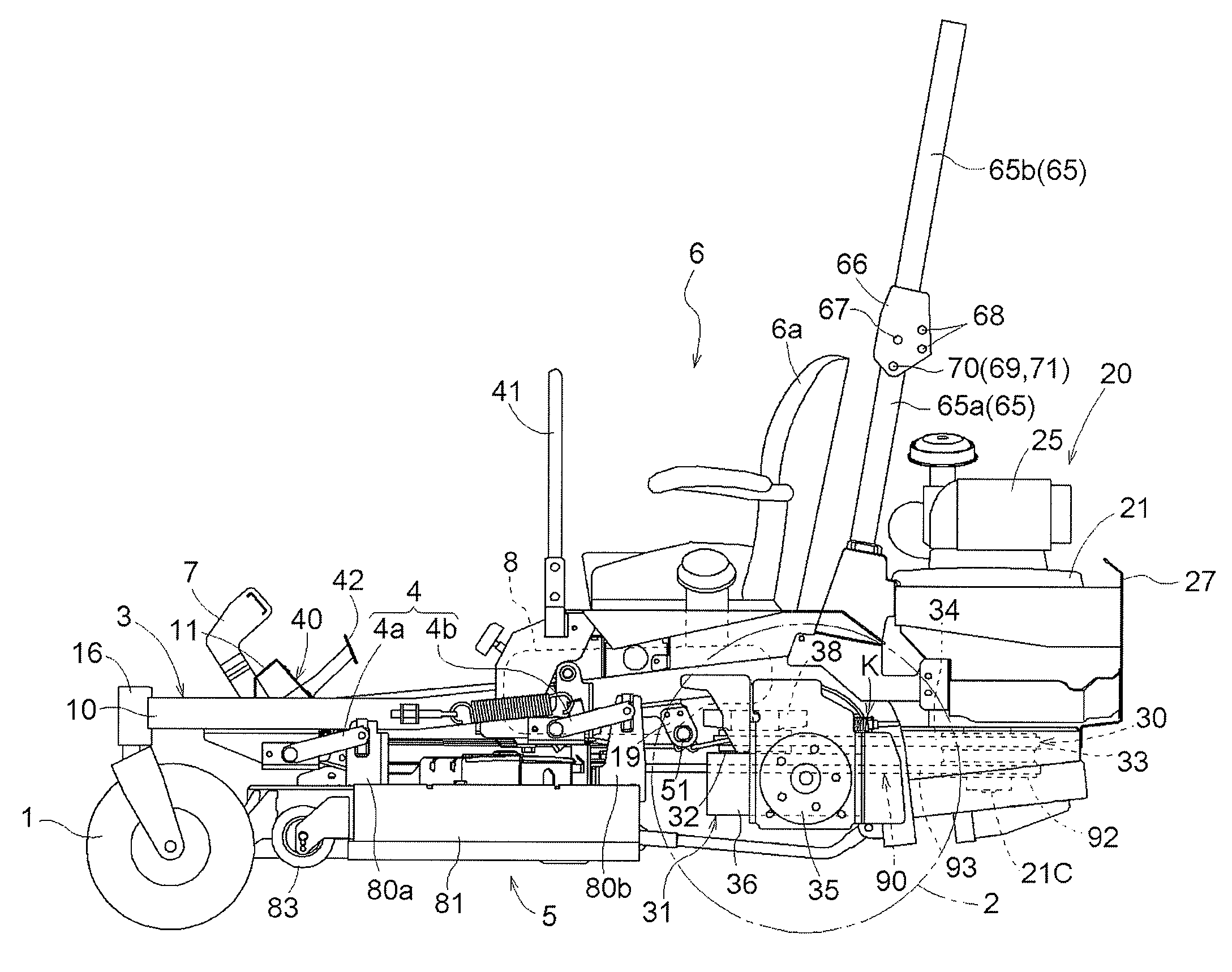
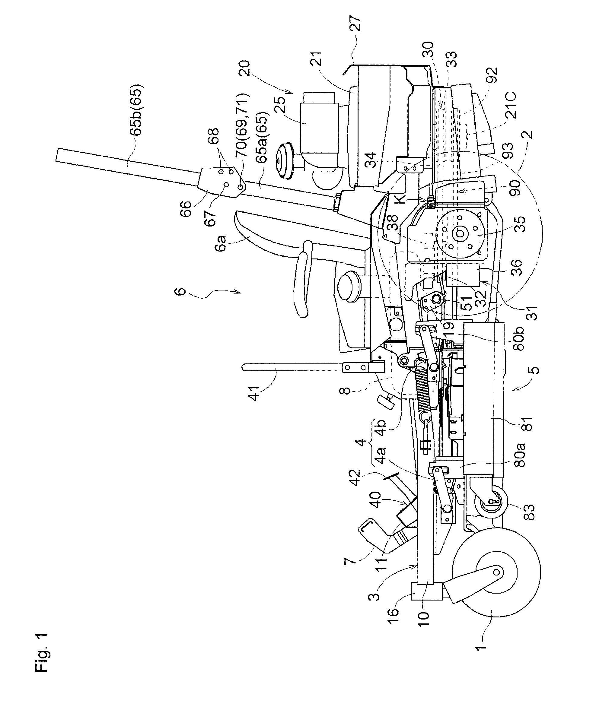
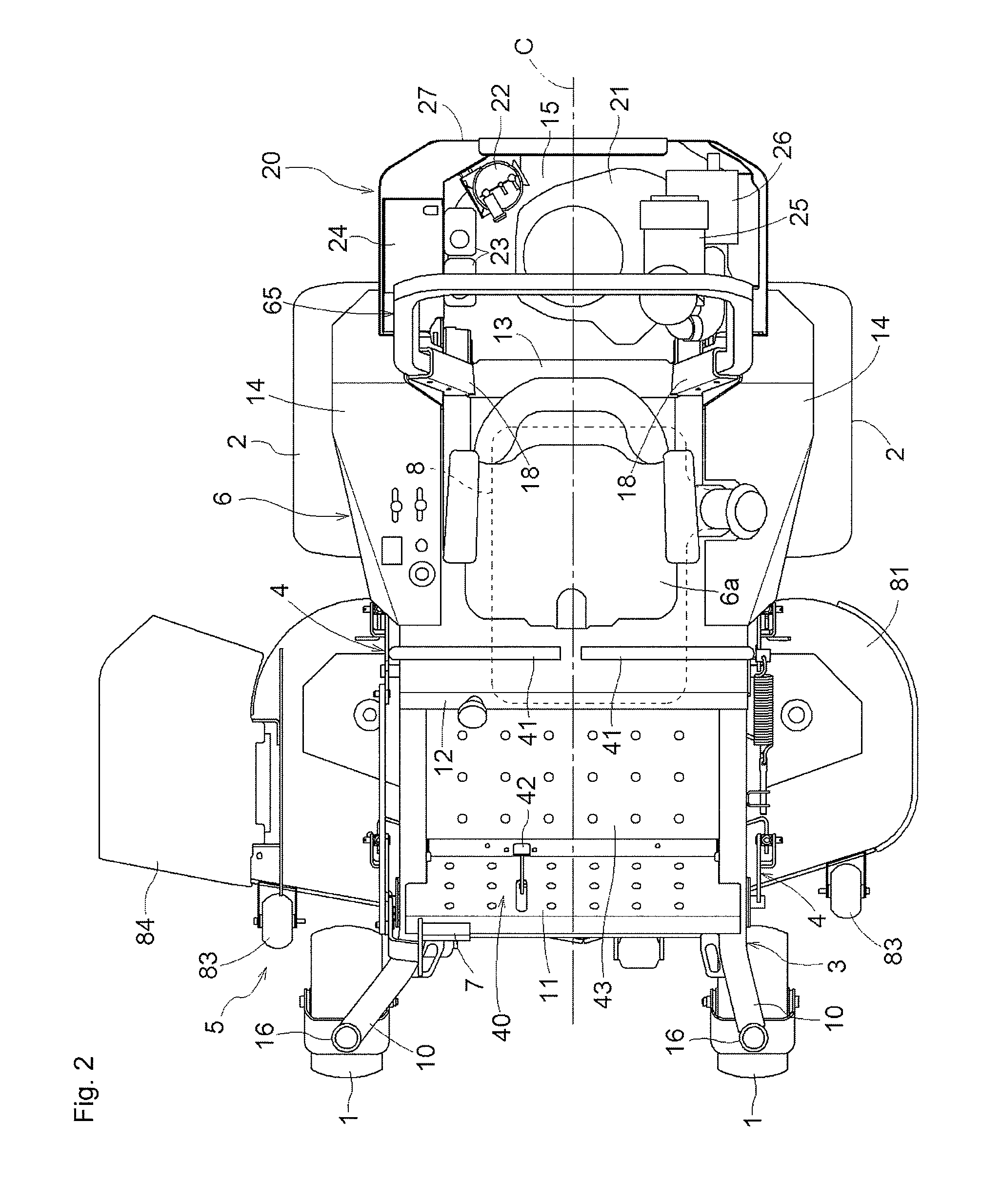
[0036]Hereinafter, an embodiment of the present invention is described with reference to the drawings. FIG. 1 is a side view illustrating an entirety of a riding type mower according to the embodiment of the present invention. FIG. 2 is a plan view illustrating the entirety of the riding type mower according to the embodiment ...


PUM


Abstract

A relay shaft is rotatably provided in a lateral direction of a vehicle body on a rear side of the vehicle body with respect to a mowing apparatus and on a front side of the vehicle body with respect to a left and right pair of rear wheel drive apparatuses. A pedal coupling rod extends in the front-rear direction of the vehicle body above the mowing apparatus and connects to a brake pedal and to the relay shaft. A left brake coupling rod extends in the front-rear direction of the vehicle body and connects to a left end of the relay shaft and to an operation portion of a left rear wheel brake. A right brake coupling rod extends in the front-rear direction of the vehicle body and connects to a right end of the relay shaft and to an operation portion of a right rear wheel brake.

Description

CROSS-REFERENCE TO RELATED APPLICATIONS[0001]The present application claims priority under 35 U.S.C. §119 of Japanese Application No. 2011-183742, filed on Aug. 25, 2011, the disclosure of which is expressly incorporated by reference herein in its entirety.BACKGROUND OF THE INVENTION[0002]1. Field of the Invention[0003]The present invention is related to a riding type mower configured with a self-propelled vehicle and a mowing apparatus. The self-propelled vehicle includes a driver step provided to a front portion of a vehicle body, an engine provided to a rear portion of the vehicle body, a left-right pair of rear wheel drive apparatuses provided on a front side of the vehicle body with respect to the engine and on a rear side of the vehicle body with respect to the driver step and transmitting drive force from the engine to each of a left-right pair of rear wheels, and a left-right pair of rear wheel brakes provided to the left-right pair of rear wheel drive apparatuses respective...

Claims


Application Information

Patent Timeline
IPC IPC(8): A01D34/64A01D34/82A01D69/10A01D34/74
CPCA01D69/10
Inventor YAMADA, MASAHIROTOGOSHI, YOSHIKAZUSATO, EIJI
Owner KUBOTA LTD
Why Eureka
Try Eureka