Umbrella carrier
- Summary
- Abstract
- Description
- Claims
- Application Information
AI Technical Summary
Benefits of technology
Problems solved by technology
Method used
Image

Examples
Embodiment Construction
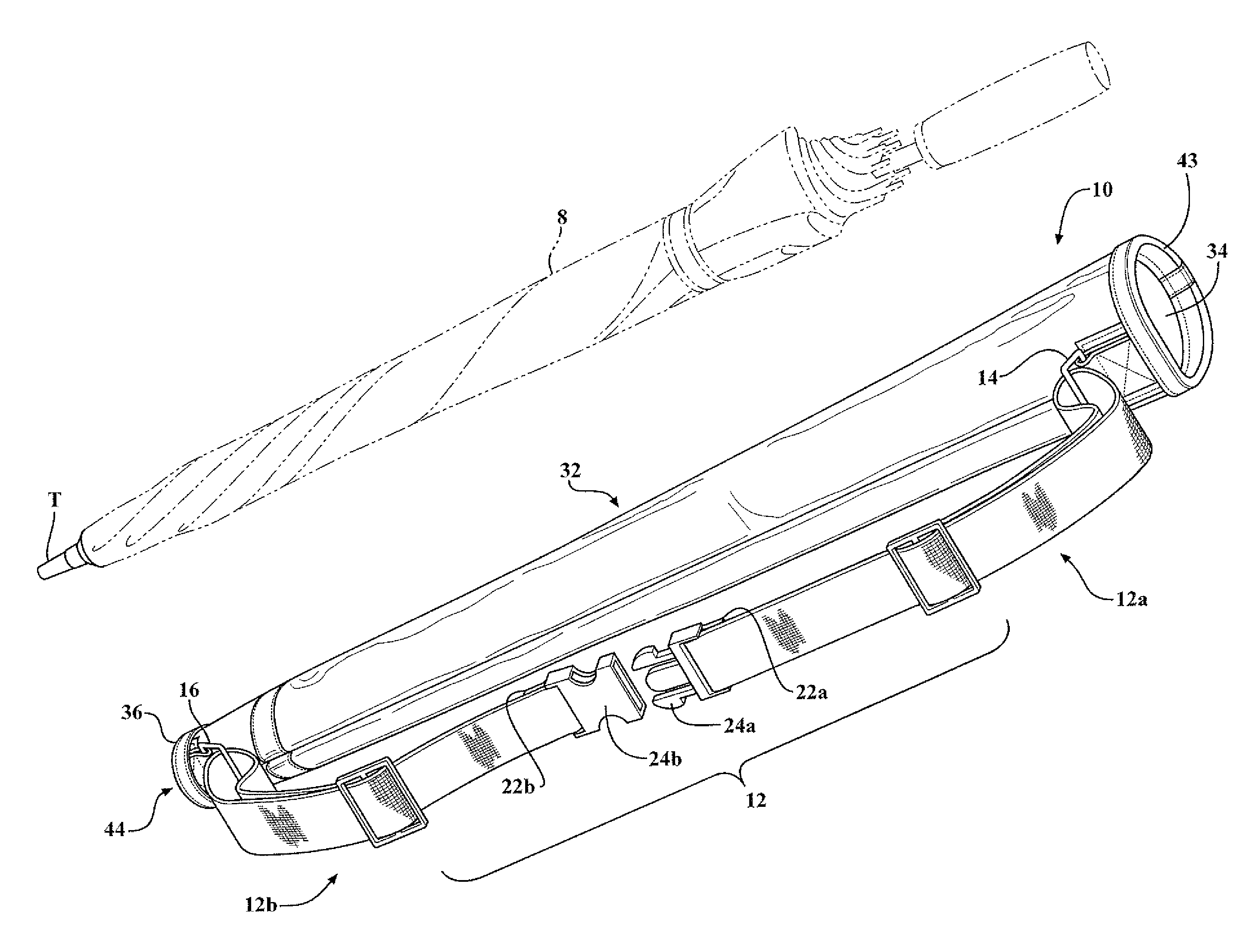
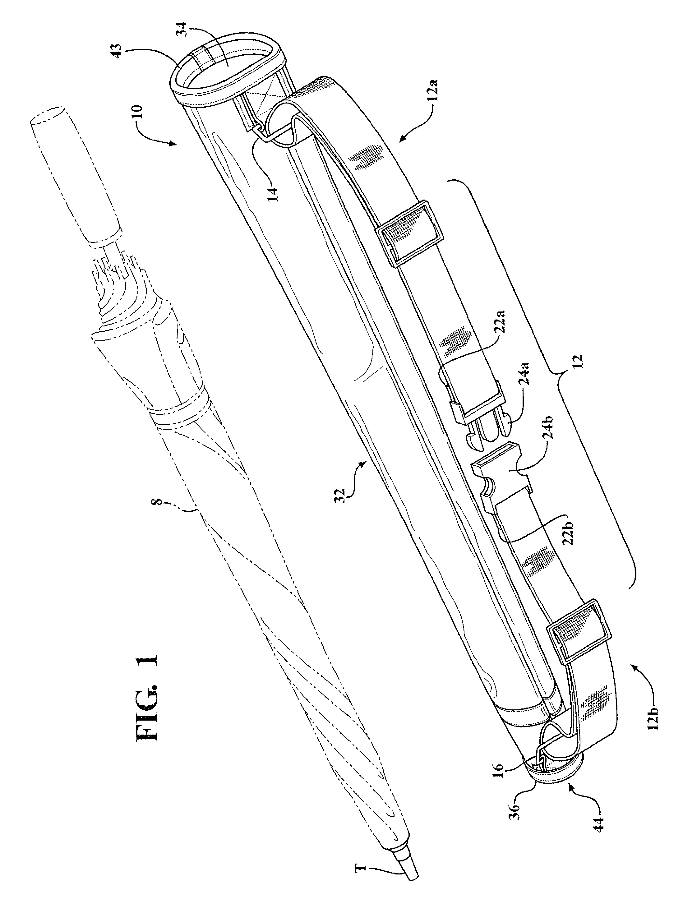
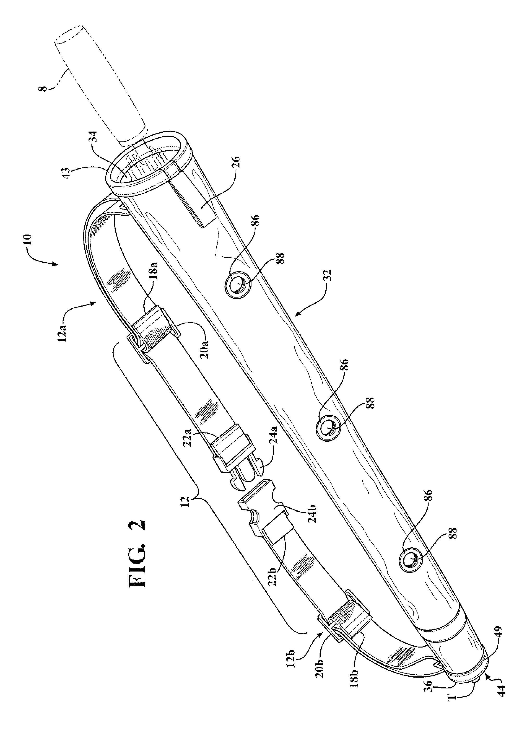
[0021]Referring to the Figures, wherein like numerals indicate like or corresponding parts throughout the several views, an umbrella carrier for holding and transporting an umbrella 8 is generally shown at 10 in FIGS. 1 and 2. The user can stow and transport the umbrella 8 in the carrier 10 when the umbrella 8 is wet. The carrier 10 manages water received therein from the wet umbrella to reduce any potential for the user to get wet.
[0022]Referring to FIGS. 1 and 2, the carrier 10 comprises a sheath 32 having an open proximal end 34 for receiving the umbrella 8. The sheath 32 extends from the proximal end 34 to a distal end 36. The sheath has a slight taper from the open proximal end 34 to the distal end 36 and defines an interior space for holding the umbrella 8. The sheath 32 is dimensioned to snugly hold the umbrella 8 in the interior space when the umbrella 8 is collapsed and placed therein. The sheath 32 acts as a barrier between the umbrella 8 and the user. The sheath 32 is fle...
PUM
 Abstract
Description
Claims
Application Information