Fuel supply system

a technology of fuel supply system and fuel filter, which is applied in the direction of liquid fuel feeder, machine/engine, mechanical equipment, etc., can solve the problems of high-resource and costly water filter or treatment system, thermal problems, and fuel contamination in the fuel filter

Inactive Publication Date: 2013-02-28
DAIMLER AG
View PDF4 Cites 5 Cited by
  • Summary
  • Abstract
  • Description
  • Claims
  • Application Information

AI Technical Summary

Benefits of technology

[0006]It is the principal object of the present invention to provide an improved fuel supply system with a fuel filter including means for collecting the water separated from the fuel and disposing the water in an environmentally friendly and reliable process.

Problems solved by technology

A problem here is that the water separated in the fuel filter is generally contaminated with fuel.
Since non-combusted fuel may not be discharged into the environment, high-resource and costly water filters or treatment systems for example must be used for the disposal of the collected water.
The injection of the water into the exhaust gas system however can lead to thermal problems in the exhaust gas after-treatment process, as the water concentration can fluctuate very greatly and unpredictably in the range from 0 to 100%.

Method used


Image

  • Fuel supply system
  • Fuel supply system

Examples


Embodiment Construction

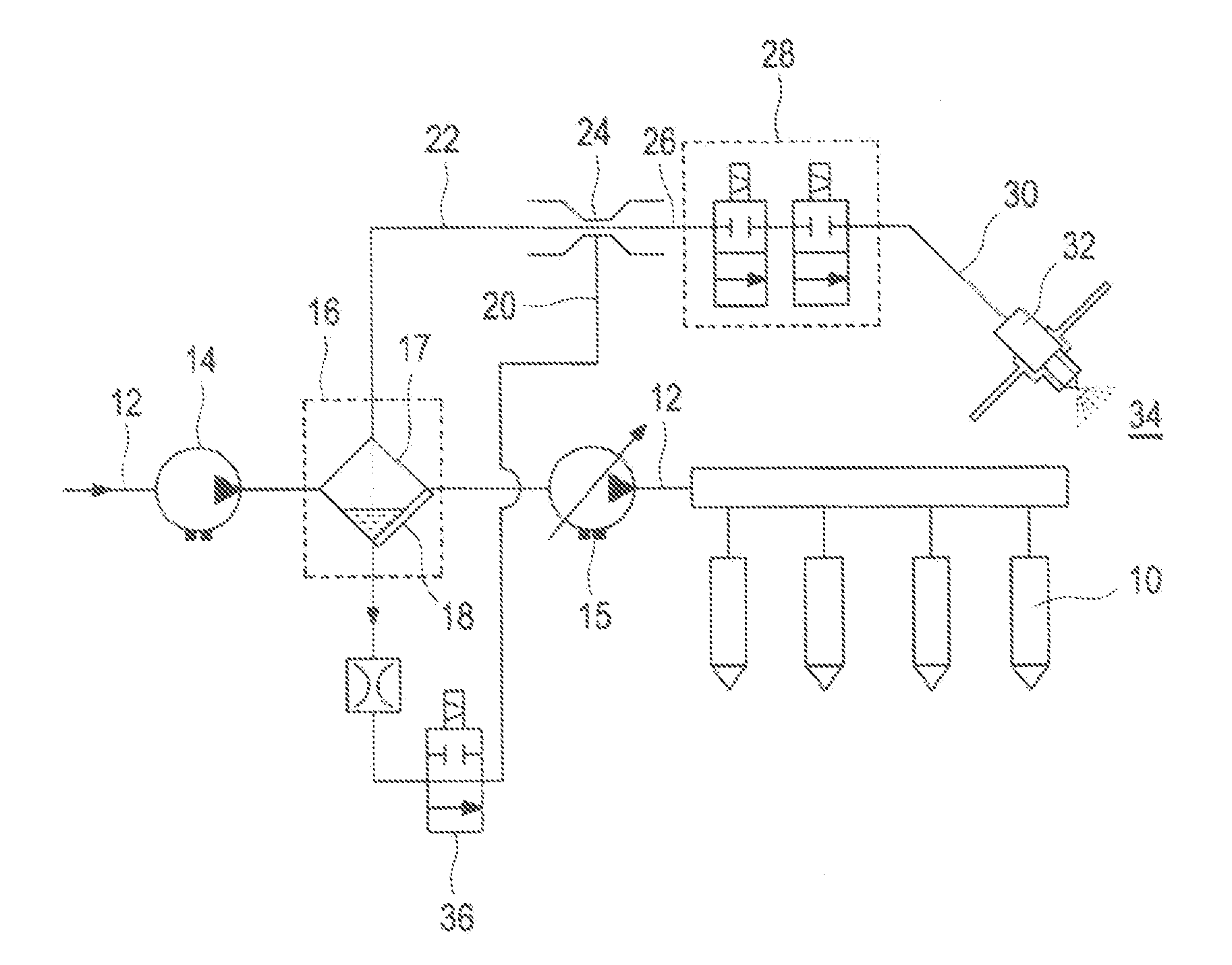
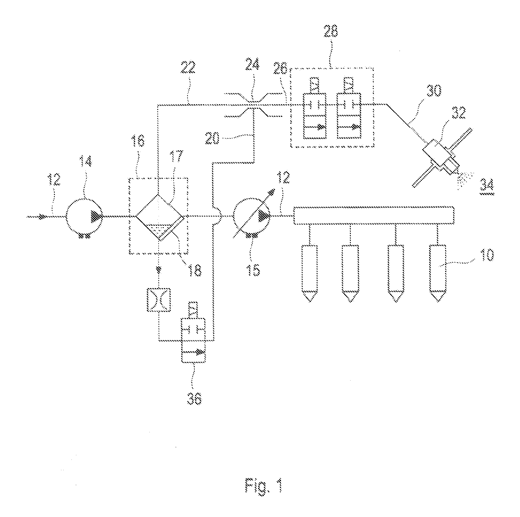
[0019]Fuel is supplied to a fuel injection device 10 of an internal combustion engine (not shown) via a fuel supply pipe 12. The internal combustion engine is for example a diesel engine but the fuel supply system according to the invention is not to be limited to this particular application.

[0020]A fuel filter 16 provided with a water separator 17 is arranged in the fuel supply pipe 12 in a manner known per se, The fuel is conveyed by means of a fuel pump 14 arranged upstream of the fuel filter 16 and / or a fuel pump 15 arranged downstream of the fuel filter 16 to the fuel injection device 10 of the internal combustion engine.

[0021]In order to detect the quantity of water which has collected in the fuel filter 16, a water level sensor 18 is provided which is preferably incorporated in, or on, the housing of the fuel filter 16.

[0022]The inventive concept for automatic removal of the water which has collected in the fuel filter 16 or in the water separator 17 thereof will now be expla...


PUM


Abstract

In a fuel supply system with a fuel supply pipe for pumping fuel from a fuel tank via a fuel supply pipe to a fuel injection device of an internal combustion engine, wherein a fuel filter including a water separator is arranged in the fuel supply pipe for removing water collected in the water separator and injecting it into an exhaust gas system, a fuel/water discharge arrangement is provided which includes a main pipe connected to the fuel filter, a branch pipe connected to a water collection region of the fuel filter and a mixing device arranged in the main pipe for mixing water to a fuel flow in the main pipe for injection into the exhaust gas system

Description

[0001]This is a Continuation-In-Part application of pending international patent application PCT / EP2010 / 001516 filed Dec. 9, 2010 and claiming the priority of German patent application 10 2010 011 915.6 filed Mar. 18, 2010.BACKGROUND OF THE INVENTION[0002]The invention relates to a fuel supply system for an internal combustion engine with a fuel supply line extending from a fuel tank to a fuel injection device of the internal combustion engine and including a water separator and water discharge arrangement for discharging the water into the engine exhaust system.[0003]The use of fuel filters with water separators in the fuel supply pipe to the fuel injection device of an internal combustion engine has been known for a long time. The water must thereby be regularly emptied from the fuel filter or the water separator. A problem here is that the water separated in the fuel filter is generally contaminated with fuel. Since non-combusted fuel may not be discharged into the environment, h...

Claims


Application Information

Patent Timeline
Patent Type & Authority Applications(United States)
IPC IPC(8): B05B15/00F02M37/28F02M37/32
CPCF01N3/0253F02M37/221F01N3/36F01N3/04F02M37/32F02M37/28
Inventor ORTLEPP, THORSTENGRUNENBERG, CHRISTIANROUTIER, EMMANUEL
Owner DAIMLER AG
Why Eureka
Try Eureka