
Hydraulic seal assembly for a thermoplastic material dispensing valve assembly

Inactive Publication Date: 2013-02-28
ILLINOIS TOOL WORKS INC
View PDF33 Cites 2 Cited by
  • Summary
  • Abstract
  • Description
  • Claims
  • Application Information

AI Technical Summary

Benefits of technology

The present invention provides an improved seal assembly for use in hot melt adhesive or thermoplastic material dispensing valve assemblies. The seal assembly comprises a casing with a primary seal member, a secondary seal member, and a viscous silicone grease or similar fluid inside the casing. The viscous silicone grease effectively distributes pressure forces, preventing any tendency of leakage. It also acts as a lubricant reducing friction and wear of the seal members, increasing the operative cycles of the hot melt adhesive valve dispensing assembly.

Problems solved by technology

To the contrary, when the structural integrity of the seal mechanism is in fact eventually compromised and effectively fails, leakage of the hot melt adhesive or other thermoplastic material out from the seal cartridge and the dispensing valve assembly will occur.
As can therefore be appreciated, each time this hardened and abrasive mass reciprocates past the seal mechanism during the aforenoted cyclic operations, the hardened and abrasive mass will begin to erode the seal mechanism eventually leading to its failure.
When failure of the seal mechanism does in fact occur, substantial leakage of the hot melt adhesive or other thermoplastic material past the seal mechanism will also occur whereby the leaked hot melt adhesive or other thermoplastic material will eventually leak out from the weep hole defined within the seal cartridge thereby indicating to the operator that the seal mechanism has in fact failed and that the valve dispensing assembly needs to be replaced.

Method used


Image

  • Hydraulic seal assembly for a thermoplastic material dispensing valve assembly
  • Hydraulic seal assembly for a thermoplastic material dispensing valve assembly
  • Hydraulic seal assembly for a thermoplastic material dispensing valve assembly

Examples


Embodiment Construction

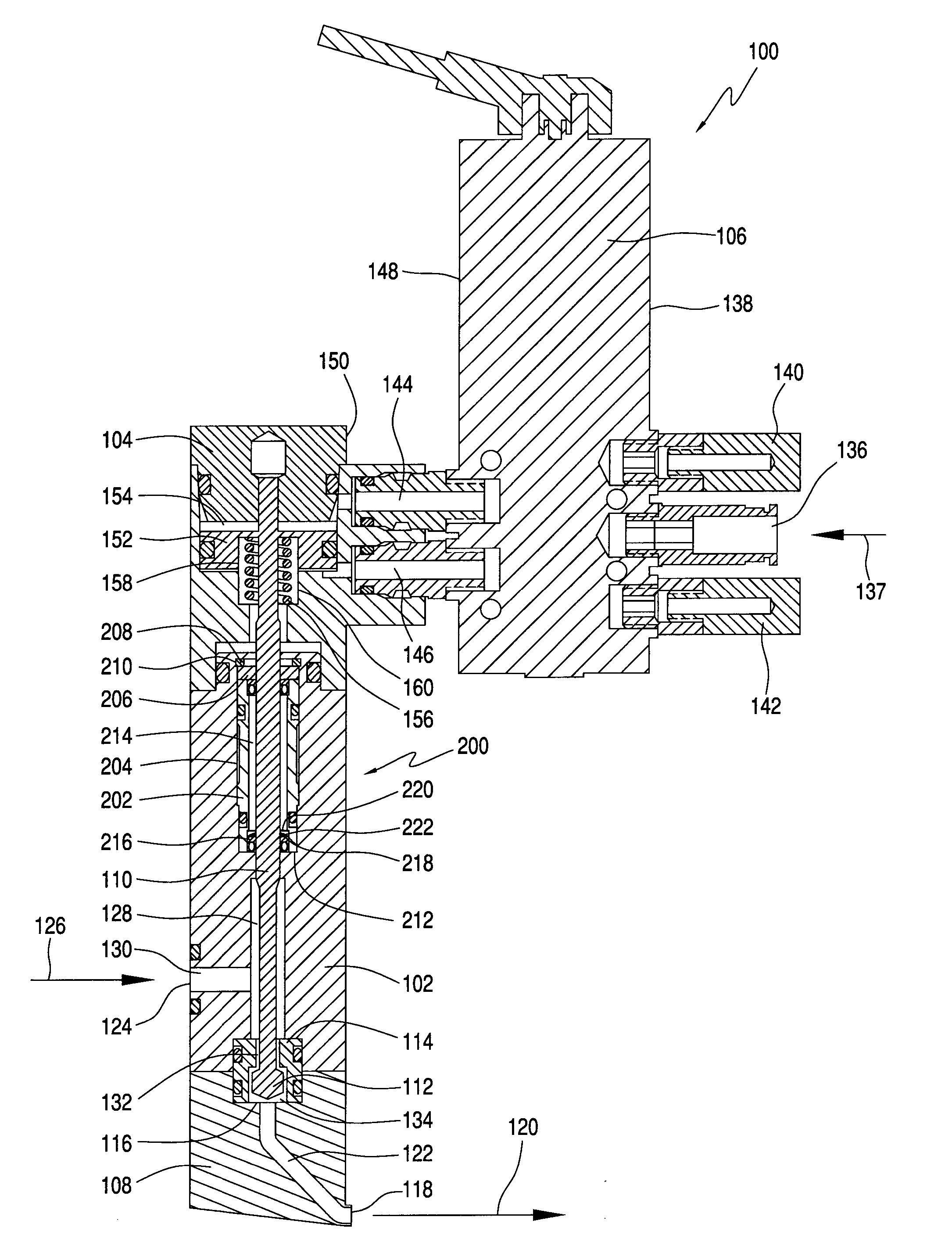
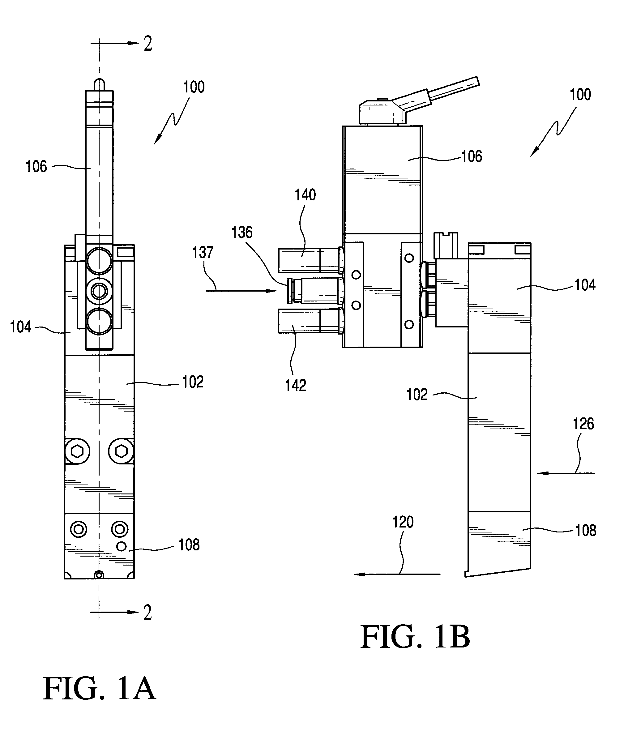
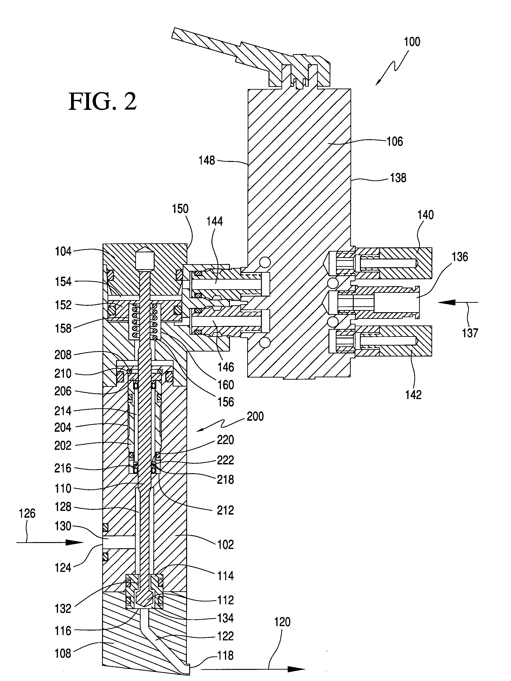
[0012]Referring now to the drawings, and more particularly to FIGS. 1A and 1B thereof, a new and improved hot melt adhesive or other thermoplastic material dispensing valve assembly, incorporating a new and improved seal assembly of the present invention therewithin, and constructed in accordance with the principles and teachings of the present invention, is disclosed and is generally indicated by the reference character 100. More particularly, the new and improved dispensing valve assembly 100 of the present invention can be used to dispense hot melt adhesives or other thermoplastic materials onto an underlying substrate or product as the substrate or product passes beneath the dispensing valve assembly 100 along a product processing line during a hot melt adhesive or other thermoplastic material application or dispensing operation or cycle. The dispensing valve assembly 100 is seen to comprise a valve body section or housing 102 containing a dispensing valve as will be more fully ...


PUM


Abstract

A seal assembly, for use within a hot melt adhesive or other thermoplastic material dispensing valve assembly, comprises a sealing cartridge comprising a first primary seal, a secondary seal, and a viscous incompressible silicone grease disposed internally within the sealing cartridge. The viscous silicone grease effectively distributes the pressure forces such that internal pressure forces within the silicone grease are substantially equal to the external pressure forces of the hot melt adhesive whereby a pressure differential across the primary seal member is effectively eliminated thereby effectively eliminating the tendency for leakage of the hot melt adhesive or other thermoplastic materials.

Description

CROSS REFERENCE TO RELATED PATENT APPLICATION[0001]This patent application is related to, based upon, and effectively a utility / non-provisional patent application conversion from United States Provisional Patent Application Ser. No. 61 / 573,089, which was filed on Aug. 31, 2011, the filing date benefits of which are hereby claimed.FIELD OF THE INVENTION[0002]The present invention relates generally to seal mechanisms, and more particularly to a hydraulic seal assembly for use within a hot melt adhesive or other thermoplastic material dispensing valve assembly.BACKGROUND OF THE INVENTION[0003]In conventional liquid dispensing systems, such as, for example, those systems outputting or discharging hot melt adhesives or other thermoplastic materials, a dispensing valve assembly, comprising a reciprocally moving valve stem having a valve member fixedly disposed thereon and operatively associated with a valve seat, is usually employed so as to in fact permit the dispensing of the hot melt a...

Claims


Application Information

Patent Timeline
IPC IPC(8): F16K1/42F16J15/40F16J15/16B05B15/00
CPCB05C5/027F16J15/002F16J15/48F16J15/3236F16J15/162
Inventor MCGUFFEY, GRANT
Owner ILLINOIS TOOL WORKS INC
Learn More