Apparatus and method for determining the 3D coordinates of an object and for calibrating an industrial robot

Inactive Publication Date: 2013-02-28
STEINBICHLER OPTOTECHN
View PDF2 Cites 32 Cited by
  • Summary
  • Abstract
  • Description
  • Claims
  • Application Information

AI Technical Summary

Benefits of technology

[0027]This method makes it possible to use only the position of the robot for the global registration of the respective shot. This is in particular advantageous when it is not possible that the one reference camera or the plu

Problems solved by technology

The method is, however, possibly not sufficiently accurate with larger objects with little surface structure.
The additional use of collimating marks which are applied to the object in the overlap regions and which form tie points also frequently does not provide any sufficient improvement.
The accuracy of this robot position information is, however, as a rule not sufficient for the purposes of global registration.
A further disadvantage arises w

Method used


Image

  • Apparatus and method for determining the 3D coordinates of an object and for calibrating an industrial robot
  • Apparatus and method for determining the 3D coordinates of an object and for calibrating an industrial robot

Examples


Embodiment Construction

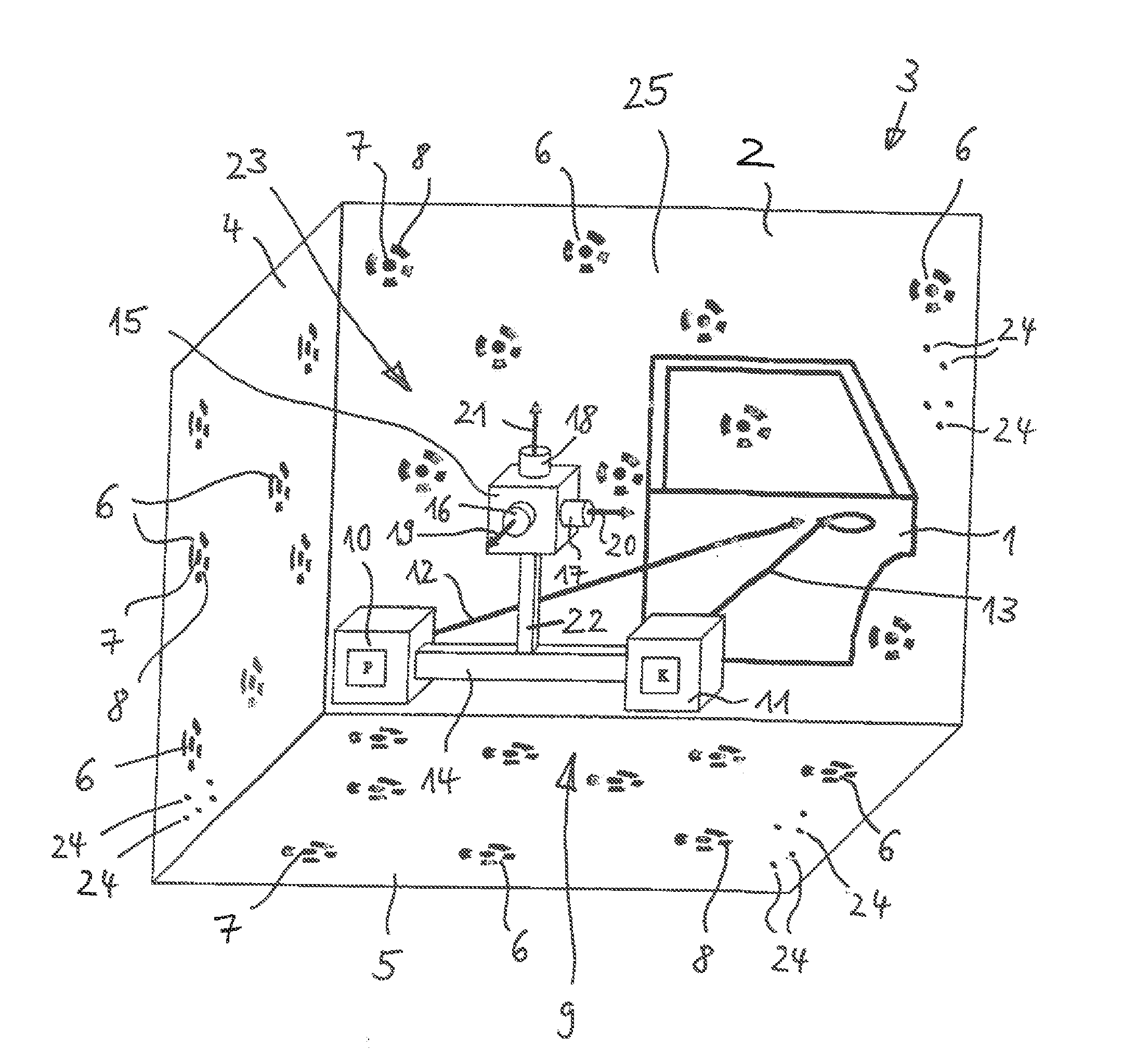
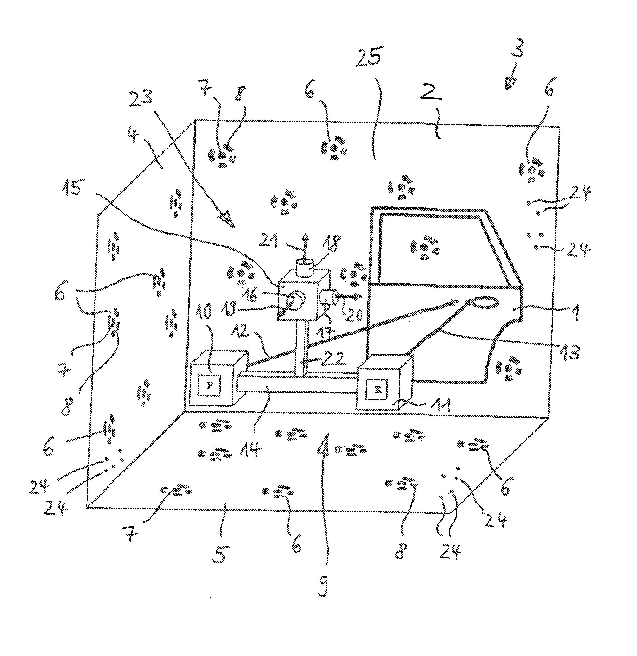
[0030]The measurement setup shown in FIG. 1 serves to determine the 3D coordinates of the front side of an object 1, namely of a motor vehicle door (body shell door). The object 1 is positioned in front of a rear wall 2 of a measuring cell 3. The measuring cell 3 includes the rear wall 2, the left side wall 4 and the base wall 5. The measuring cell 3 furthermore includes a right side wall, a rear wall and a top wall (not shown in the drawing).

[0031]Reference marks 6 which are intrinsically coded are arranged at the walls of the measuring cell 3, and reference marks 24 which are not intrinsically coded, but which are arranged spatially with respect to one another such that this spatial arrangement contains a coding. The reference marks 6, 24 form a field 25 of reference marks. Each reference mark 6 which is intrinsically coded includes an unchanging, non-encoding element and a changing, encoding element. The non-encoding element is formed by a circle 7 which is located at the center ...


PUM


Abstract

An improved apparatus for determining the 3D coordinates of an object (1) includes a projector (10) for projecting a pattern onto the object (1), a camera (11) connected to the projector (10) for taking the object (1), and a reference camera (16) connected to the projector (10) and to the camera (11) for taking one or more reference marks (6, 24) of a field (25) of reference marks (only FIGURE).

Description

BACKGROUND OF THE INVENTION[0001]The invention relates to an apparatus for determining the 3D coordinates of an object and to a method for determining the 3D coordinates of an object. The invention furthermore relates to a method for calibrating an industrial robot.[0002]In an already known method for determining the 3D coordinates of an object, the object is taken using a light fringe projection system. The light fringe projection system includes a projector for projecting a light fringe pattern onto the object and a camera for taking the light fringe pattern radiated back from the object. The shot is evaluated by an evaluation system which includes a computer, in particular a PC.[0003]Since a single shot is as a rule not sufficient to satisfy the measuring demands and / or to detect the object completely in order to determine the 3D coordinates of the object, it is necessary to position the light fringe projection system at different taking positions in space and to transfer the sho...

Claims


Application Information

Patent Timeline
IPC IPC(8): H04N13/00
CPCG01B21/042G01B11/25
Inventor STEINBICHLER, MARCUSMAYER, THOMASDAXAUER, HERBERT
Owner STEINBICHLER OPTOTECHN
Why Eureka
Try Eureka