

Planar lighting device
a lighting device and planar technology, applied in the direction of planar/plate-like light guides, lighting and heating apparatus, instruments, etc., can solve the problem of difficulty in ensuring that the rays of light can reach the end of the light guide plate, and achieve the effect of reducing the leakage of light and enhancing the propagation ra
- Summary
- Abstract
- Description
- Claims
- Application Information
AI Technical Summary
Benefits of technology
Problems solved by technology
Method used
Image

Examples
example
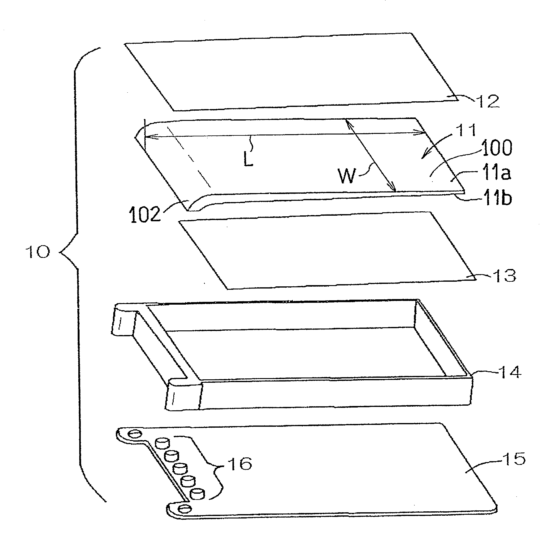
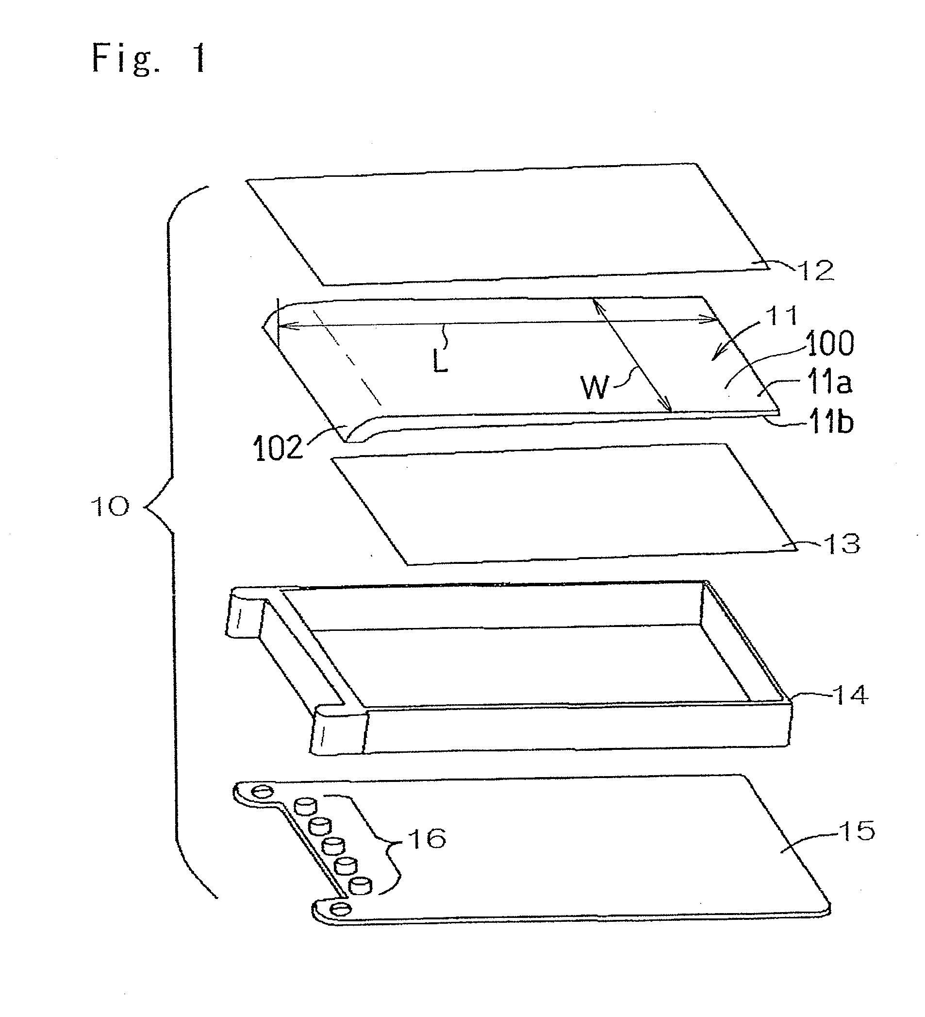
Light Guide Plate
[0038]Using “Iupilon HL-4000”, (manufactured and tradenamed by Mitsubishi Engineering-Plastic Corporation of Japan, as a material for the light guide plate body, the material was supplied to an injection molding machine to form the light guide plate of a predetermined shape under conditions of 240° C. in cylinder temperature, 80° C. in mold temperature and 180 ton in mold clamp pressure.
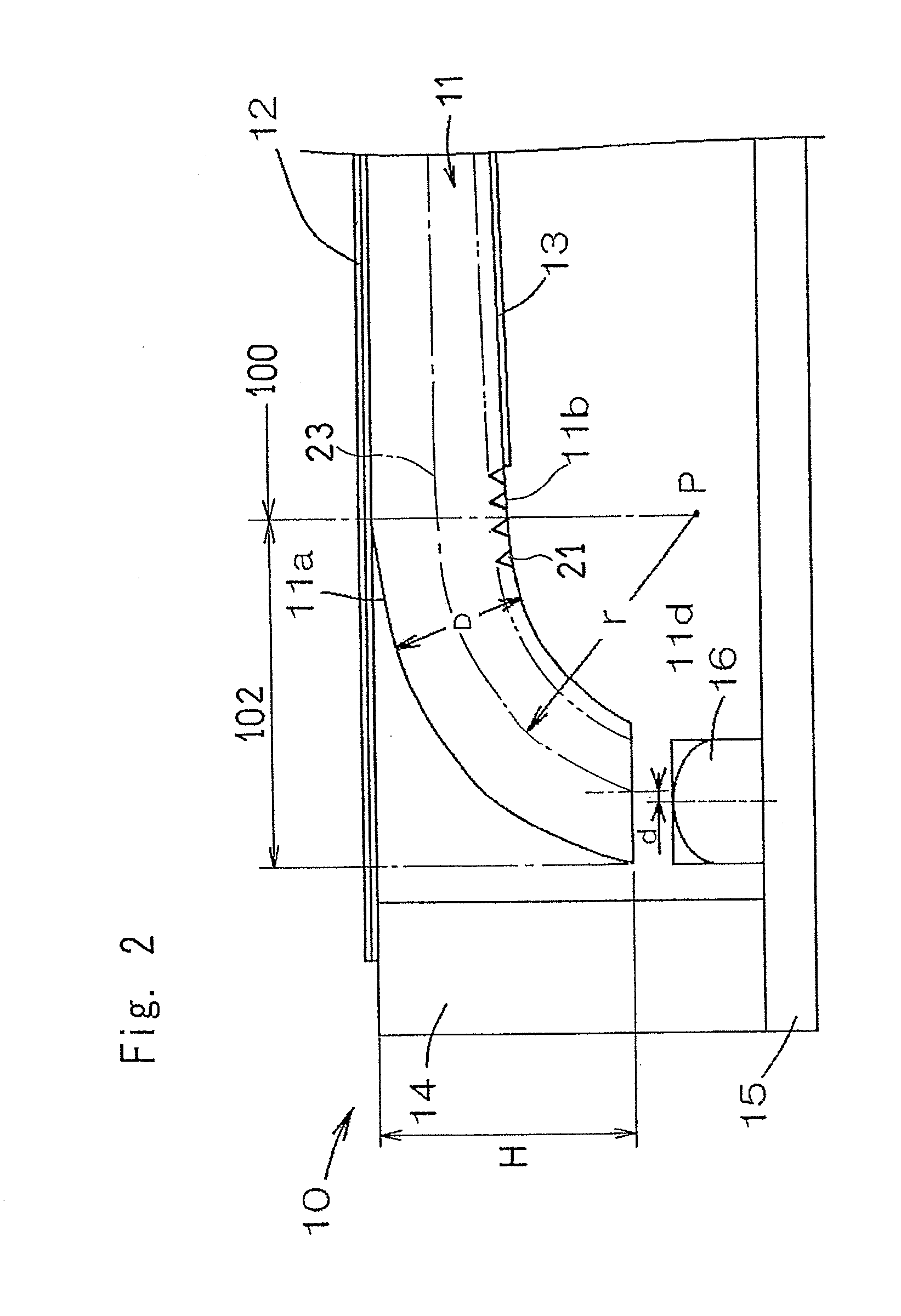
[0039]The light guide plate so manufactured was 55.0 mm in width W and 85.0 mm in length L, representing the wedge shaped sectional shape, when viewed in section taken in a direction lengthwise thereof, with the thickness thereof varying 3.0 mm to 1.0 mm in the lengthwise direction, in which one side or a thick side of the thickness (the surface to surface distance D) was curved towards the rear surface side to define the curvedly descending portion.
[0040]Samples having the respective curvedly descending portions of the radius of curvature varying by 1.0 mm within the range of 3.0 to...
PUM
 Abstract
Description
Claims
Application Information