Cooling device for hydraulic braking systems

a technology of hydraulic braking and cooling device, which is applied in the direction of cycle brakes, cycle equipment, liquid fuel engines, etc., can solve the problems of inability to efficiently reduce temperature and danger of cyclists, and achieve the effect of improving the overheating of the conventional braking system

Inactive Publication Date: 2013-02-28
ASHIMA LTD
View PDF2 Cites 4 Cited by
  • Summary
  • Abstract
  • Description
  • Claims
  • Application Information

AI Technical Summary

Benefits of technology

[0007]The main objective of the present invention is to provide a cooling device for improving overheat of the conventional braking systems.

Problems solved by technology

Consequently, the braking disc can be overheat and further reduce the friction coefficient between the lining plates and the braking disc, such that the cyclist might be dangerous when the braking system is not work.
However, the braking disc is a hollow plate which cannot generate air ventilation by the rotation of itself, thus the temperature cannot be reduced efficiently.

Method used


Image

  • Cooling device for hydraulic braking systems
  • Cooling device for hydraulic braking systems
  • Cooling device for hydraulic braking systems

Examples


Embodiment Construction

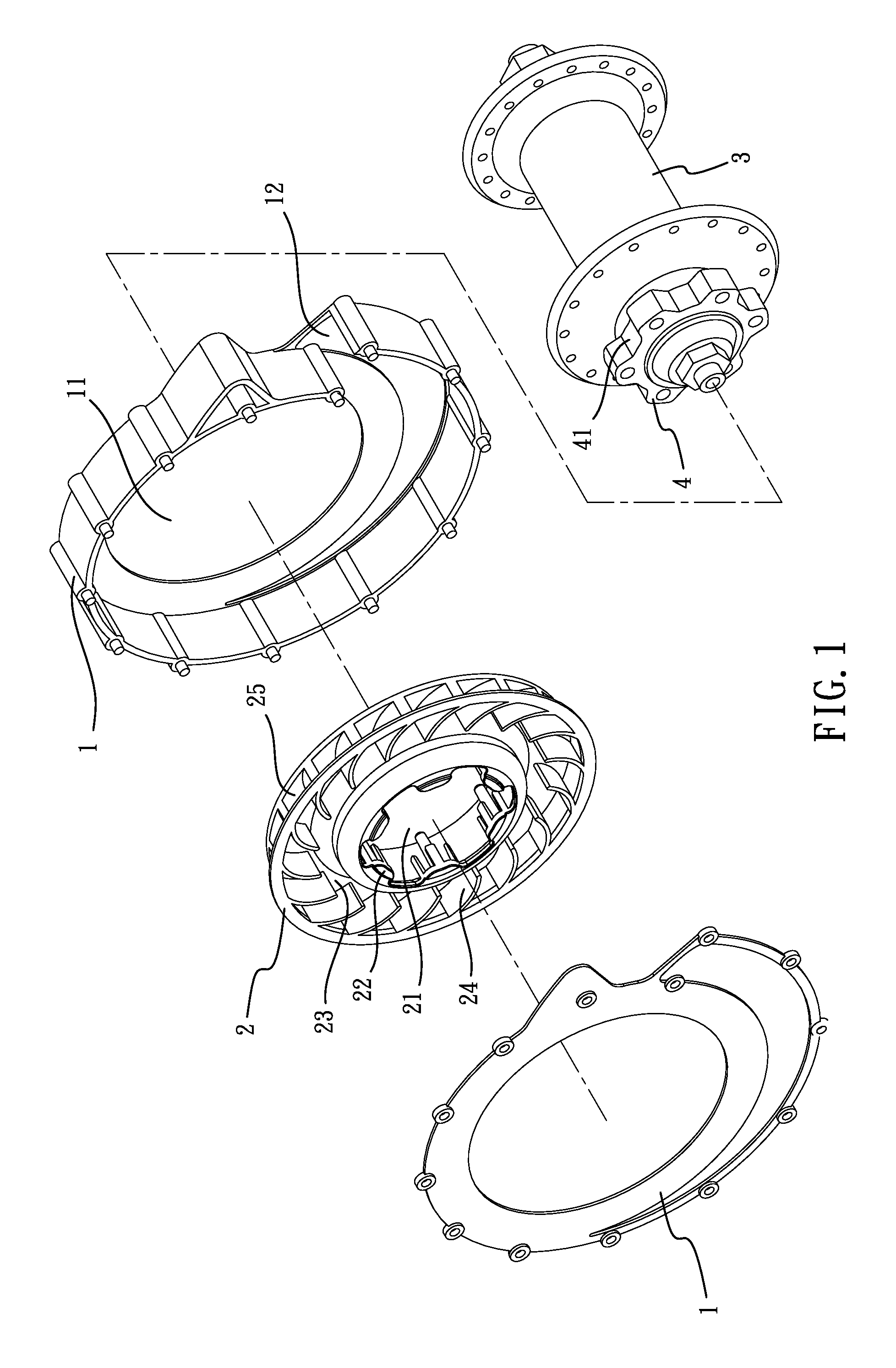
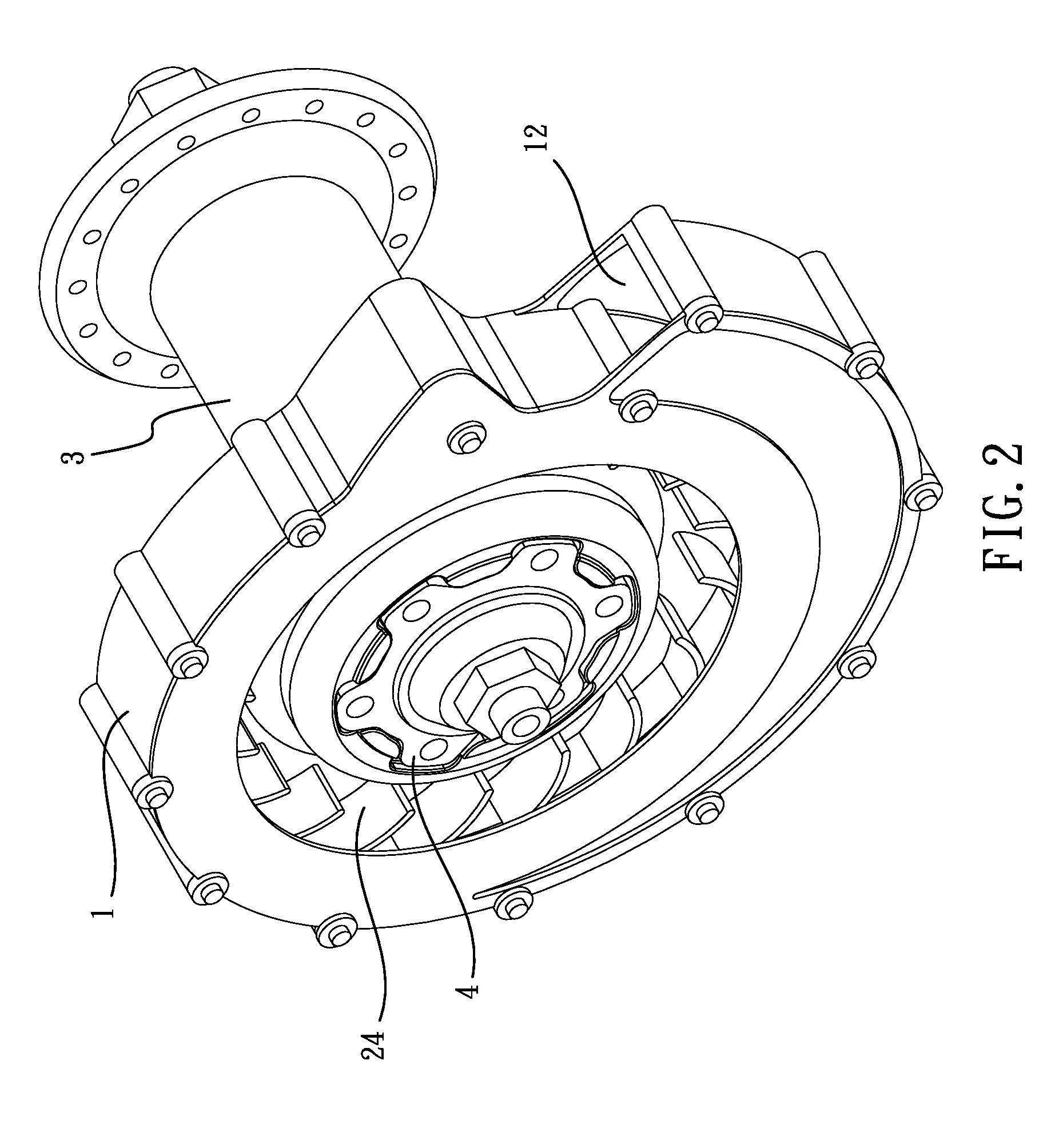
[0018]Referring to the drawings and initially to FIGS. 1 to 3, the cooling device for hydraulic braking systems in accordance with the present invention comprises a case 1, a turbine unit 2 and a ring 4 that is connected to an end of a hub 3. The case 1 is a spiral case and a thorough hole 11 is defined therethrough. A ventilation exit 12 is defined on the case 1 and communicates the inside and the outside of the case 1, so that the air convection between the inside and the outside of the case 1 is possible. The turbine unit 2 is located and operated in the case 1 and the turbine unit 2 has a fixing hole 21 which communicates with the through hole 11. A plurality of protrusions 22 is located at an inside of the fixing hole 21 and each protrusion 22 is an oval protrusion. The conjunction portions between the two sides of the protrusion 22 and the fixing hole 21 are two recesses so as to be pivotably connected with the ring 4. A guide groove 23 is defined in a side of the turbine unit...


PUM


Abstract

A cooling device for hydraulic braking systems includes a case, a turbine unit, and a ring which is connected to an end of a hub. The case has a thorough hole and a ventilation exit communicating inside and outside of the case is defined on the case. The turbine unit is located in the case and has a fixing hole which communicates with the through hole. The ring is connected to the fixing hole of the turbine unit. The ring drives the turbine unit which generates air flows in the case. The air flows flow to the outside of the case via the ventilation exit to remove the heat of the braking system.

Description

BACKGROUND OF THE INVENTION[0001]1. Field of the Invention[0002]The present invention relates to cooling device for hydraulic braking systems, and more particularly to a cooling action to the hydraulic braking system by air ventilation.[0003]2. Description of Related Art[0004]Bicycles are very popular today. When a cyclist rides a bicycle along an uphill, the braking system ensures the safety for the cyclist and the modern braking system is operated by hydraulic system which drives the lining plates in the braking system to contact the braking disc to slow down and stop the wheel. For the reason of safety, it is necessary to brake frequently when the cyclist rides along a downhill. Consequently, the braking disc can be overheat and further reduce the friction coefficient between the lining plates and the braking disc, such that the cyclist might be dangerous when the braking system is not work.[0005]Some manufacturers set recesses defined in the braking disc to allow air to flow thr...

Claims


Application Information

Patent Timeline
Patent Type & Authority Applications(United States)
IPC IPC(8): F01D25/24
CPCB60T5/00F04D29/582F16D2055/0008F16D65/0081F16D65/847B62L3/023
Inventor MOORE, WAYNE-IAN
Owner ASHIMA LTD
Why Eureka
Try Eureka