Dynamic cable for ocean engineering

A dynamic cable and marine engineering technology, applied in the direction of submarine cables, insulated cables, cables, etc., can solve problems such as cable breakage, poor anti-overheating effect of the cable core, melting, etc., and achieve the effect of preventing the cable core from overheating

Pending Publication Date: 2022-07-22
杨宁
View PDF1 Cites 0 Cited by
  • Summary
  • Abstract
  • Description
  • Claims
  • Application Information

AI Technical Summary

Problems solved by technology

[0002] Cables used in existing marine engineering do not perform well in resisting the impact of water and waves
[0003] In view of the above problems, as far as the technical problem of the poor tensile effect of the existing dynamic cables for marine engineering is concerned, after a large number of searches, a new type of dynamic cable for marine engineering with the patent number CN202120185337. The inner part of the wrapping layer is wrapped with an outer stainless steel tube, and the middle part of the outer stainless steel tube is wrapped with an inner stainless steel tube, and an optical fiber is installed between the outer stainless steel tube and the inner stainless steel tube, and the No. Insulation layer, and No. 2 copper conductor is wrapped inside the No. 2 insulation layer. Rubber blocks are uniformly and fixedly installed on the No. 2 insulation layer and No. 2 copper conductors, and rubber balls are contacted and rolled between the rubber blocks. Extension columns are fixedly installed at both ends, and springs are fixedly installed in the middle of the extension columns, abutment balls are fixedly installed at the ends of the extension columns away from each other, and a main force core is installed inside the No. 2 copper conductor; this patent solves the problem of It solves the technical problem that the cables used in the existing ocean engineering have poor effects in resisting the impact of water and waves, but the technical solution provided by this patent is not effective in preventing overheating in the cable core. In the process of long-distance power transmission, submarine cables are prone to generate heat due to resistance, which will age or even melt the insulating layer wrapping the cable, and eventually cause the technical problem of cable breakage

Method used


Image

  • Dynamic cable for ocean engineering
  • Dynamic cable for ocean engineering
  • Dynamic cable for ocean engineering

Examples


Embodiment 1

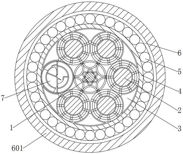
[0037] see Figure 1-2 , in the embodiment of the present invention, a dynamic cable for marine engineering, comprising:

[0038] The power core 1 and the inner sheath 4, a plurality of overheating prevention components 7 that can prevent the cable core from overheating are arranged between the middle end of the left inner wall of the inner sheath 4 and the left end of the power supply core 1. The overheating prevention component 7 includes: a casing 8, The inner shell 9, the support bar 10, the thermal conduction component 11 that can guide the cable core in time after the heat is generated, and the cooling component 12 that can be cooled in time after the cable core is heated, the middle end of the left inner wall of the inner sheath 4 is connected to the power core 1. A number of outer shells 8 are arranged between the left ends of the outer shell 8, an inner shell 9 is fixedly installed in the inner center of the outer shell 8, a support bar 10 is fixedly installed between...

Embodiment 2

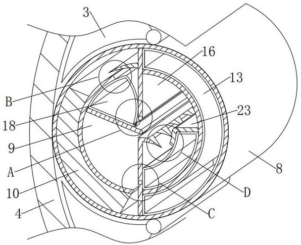
[0053] see Figure 2-4 and Figure 7 The difference between the embodiment of the present invention and the embodiment 1 is that the main air bag 13 is in the shape of a long fan with left concave and right convex on a longitudinal section, and the top and bottom ends of the main air bag 13 are under normal conditions. statically located at the top and bottom ends of the shell 8;

[0054] The main airbag 13 here is to facilitate the use of its top and bottom ends. When the heat is transferred to it, the top and bottom ends are respectively inflated to the left due to the common limitation of the outer shell 8 and the inner shell 9. deformation, so as to push the upper rotating plate 16 and the cooling component 12 to move respectively, so as to absorb heat and cool down in time.

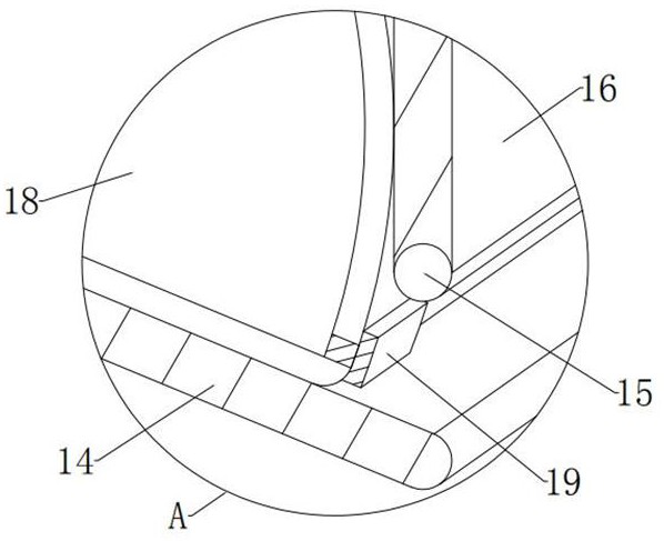
[0055] In the embodiment of the present invention, the upper limit plate 14 is in the shape of an inclined straight plate with high left and right low and an included angle of 23° with the horizont...

Embodiment 3

[0063] see figure 2 and Figure 5-7 , the difference between the embodiment of the present invention and the embodiment 1 is that the lower rotating shaft 20 is located directly above the lower groove, and the lower rotating plate 21 is vertically vertical on a longitudinal section, and the top is bent to the right. The counterclockwise rotation 90 The “¬” shape of °, the lower turning plate 21 is also in a state of vertical static equilibrium under normal conditions, and the bottom outer surface of the lower turning plate 21 is statically attached to the bottom inner wall of the housing 8 under normal conditions. 21 also has a different magnetism from that of the inner shell 9, the outer surface of the right bottom end of the lower turning plate 21 is closely attached to the outer surface of the left bottom end of the main airbag 13, and the outer surface of the lower right end of the lower turning plate 21 is in the normal state. In the case of static magnetic attraction o...


PUM


Abstract

The invention provides a dynamic cable for ocean engineering, which comprises a power supply core and an inner sheath, and is characterized in that a plurality of anti-overheating assemblies capable of preventing the cable core from overheating are arranged between the middle end of the left inner wall of the inner sheath and the left end of the power supply core in a penetrating manner; the anti-overheating assembly comprises outer shells, inner shells, supporting strips, a heat conduction assembly capable of conducting guiding in time after the cable core generates heat and a cooling assembly capable of conducting cooling in time after the cable core generates heat, a plurality of outer shells are arranged between the middle end of the left inner wall of the inner wrapping sleeve and the left end of the power supply core in a penetrating mode, and the inner shells are fixedly installed in the centers of the interiors of the outer shells; a supporting strip is fixedly installed between the left inner wall of the outer shell and the left outer wall of the inner shell. According to the dynamic cable for ocean engineering, the anti-overheating effect in the cable core can be enhanced, and in the long-distance power transmission process of the submarine cable, even if heat is generated due to resistance, the heat can be absorbed and decomposed in time, the insulation layer wrapping the cable is prevented from aging, and normal use of the cable is guaranteed.

Description

technical field [0001] The invention relates to the technical field of marine engineering, and more particularly, to a dynamic cable for marine engineering. Background technique [0002] The cables used in the existing marine engineering are not very effective in resisting the impact and tension of water and waves. [0003] In view of the above problems, regarding the technical problem of the poor tensile effect of the existing dynamic cables for marine engineering, after a lot of searches, a new type of dynamic cables for marine engineering with the patent number of CN202120185337. The inside of the cladding layer is wrapped with an outer stainless steel tube, the middle of the outer stainless steel tube is wrapped with an inner stainless steel tube, and an optical fiber is arranged between the outer stainless steel tube and the inner stainless steel tube, and the No. 1 insulating layer is evenly abutted with No. 2 Insulation layer, and the No. 2 insulating layer is wrappe...

Claims


Application Information

Patent Timeline
Patent Type & Authority Applications(China)
IPC IPC(8): H01B7/42H01B7/14H01B7/18
CPCH01B7/428H01B7/421H01B7/14H01B7/185
Inventor 杨宁
Owner 杨宁
Why Eureka
Try Eureka