
Clamping tool for cutting machining

A clamping tooling and mechanical processing technology, which is applied in the field of clamping tooling for cutting machining, can solve the problems of being difficult to be compatible with parts of various sizes, inconvenient for continuous cutting of parts, and difficult to be compatible with parts of various sizes, so as to prevent overheating high effect

Pending Publication Date: 2022-08-09
YANSHAN UNIV
View PDF4 Cites 0 Cited by
  • Summary
  • Abstract
  • Description
  • Claims
  • Application Information

AI Technical Summary

Problems solved by technology

[0002] The existing clamping tooling is difficult to be compatible with parts of various sizes, and the waste generated during cutting usually accumulates on the top of the workbench, and the workbench needs to be cleaned continuously during the cutting process, which is not convenient for continuous cutting of parts
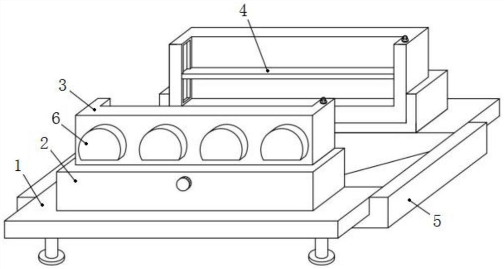
[0003] In view of the above problems, regarding the technical problem that the existing clamping tool is difficult to be compatible with parts of various sizes, etc., after a large number of searches, we found a clamping tool for laser cutting machine with the patent number CN202021552633.0, including the base and supporting feet, and also includes a fixed frame and a material box. There are two fixed frames, and the two fixed frames are fixed on the left and right sides above the base respectively. The outer side of the movable frame and the fixed frame are provided with a threaded groove 1 leading to the inside of the movable frame, the threaded groove 1 is internally threaded with a lead screw 1, the inner side of the movable frame is provided with a clamping groove, the clamping groove is provided with a splint, and the inner wall of the clamping groove There is a screw slot on the rear side, and the second screw is connected to the screw slot. The material box is attached to the front end of the base and extends to the bottom of the base; the clamping tool can adapt to parts of various sizes, which is beneficial to expand the scope of application of the tool. And it is convenient to collect waste materials, which is beneficial to improve processing efficiency, but the technical solution provided by this patent does not have the function of preventing overheating for the movable frame. When the splint inside clamps and cuts the processed parts, the high temperature generated during the cutting process The heat will be transmitted to the surface of the movable frame. When the splint is ready to be released to take out the processed parts after cutting, the operator's hands are likely to be scalded due to accidental contact with the surface of the movable frame.

Method used


Image

  • Clamping tool for cutting machining
  • Clamping tool for cutting machining
  • Clamping tool for cutting machining

Examples


Embodiment Construction

[0031] In order to illustrate the embodiments of the present invention or the technical solutions in the prior art more clearly, the following briefly introduces the accompanying drawings that need to be used in the description of the embodiments or the prior art. Obviously, the accompanying drawings in the following description These are some embodiments of the present invention. For those of ordinary skill in the art, other drawings can also be obtained according to these drawings without creative efforts.

[0032] It should be noted that in the description of the present invention, the terms "upper", "lower", "top", "bottom", "one side", "the other side", "left", "right", etc. The orientation or positional relationship is based on the orientation or positional relationship shown in the drawings, and is only for the convenience of describing the present invention and simplifying the description, and does not mean that a device or element must have a specific orientation, be c...


PUM


Abstract

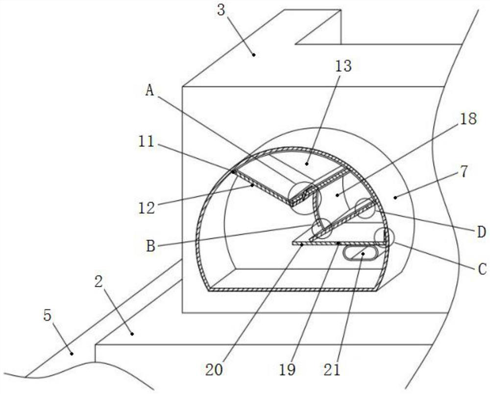
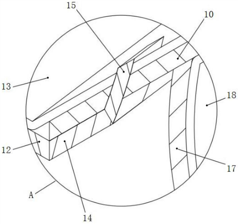
The invention relates to a clamping tool for cutting machining. The clamping tool comprises a base, a movable frame, a fixed frame and clamping plates. A plurality of anti-overheating assemblies capable of preventing the surface temperature of the movable frame from being too high are fixedly installed on the outer surface of the back side of the movable frame, and each anti-overheating assembly comprises a fixed shell, a temperature sensing assembly capable of sensing the temperature to control movement and a cooling assembly capable of cooling in time after the temperature rises. A plurality of anti-overheating assemblies are fixedly installed on the outer surface of the back side of the movable frame, and a temperature sensing assembly and a cooling assembly are movably installed at the top end and the right end of the interior of the fixed shell correspondingly. According to the clamping tool for cutting machining, the movable frame can have an anti-overheating function, when a clamping plate in the clamping tool clamps and cuts a machined part, even if high-temperature heat generated in the cutting process can be transmitted to the surface of the movable frame, the clamping plate is prepared to be loosened to take out the machined part after cutting is completed, and the movable frame can be prevented from being overheated. And the safety accident that both hands of an operator are scalded due to careless contact with the surface of the movable frame is avoided.

Description

technical field [0001] The invention relates to the technical field of cutting and clamping, in particular to a clamping tool for cutting machining. Background technique [0002] The existing clamping tooling is difficult to be compatible with parts of various sizes, and the waste generated during cutting usually accumulates above the worktable, which requires continuous cleaning of the worktable during the cutting process, which is inconvenient for continuous cutting of parts. [0003] In view of the above problems, regarding the technical problem that the existing clamping tool is difficult to be compatible with various sizes of parts, after a lot of searches, we found a clamping tool for a laser cutting machine with the patent number of CN202021552633.0, including the base and supporting feet, and also includes a fixed frame and a material box. There are two fixed frames. The two fixed frames are respectively fixed on the left and right sides above the base. The movable ...

Claims


Application Information

Patent Timeline
Patent Type & Authority Applications(China)
IPC IPC(8): B23Q11/12B23Q3/00
CPCB23Q11/126B23Q3/00B23Q2703/12Y02P70/10
Inventor 杨志南贾德诚姜锋张福成
Owner YANSHAN UNIV
Learn More