Autonomous cleaner and method of controlling the same

a cleaner and autonomous technology, applied in the field of autonomous cleaners, can solve the problems of raised area, inability to drive autonomous cleaners, and conventional autonomous cleaners not equipped with sensors

Active Publication Date: 2013-02-28
SAMSUNG ELECTRONICS CO LTD
View PDF31 Cites 26 Cited by
  • Summary
  • Abstract
  • Description
  • Claims
  • Application Information

AI Technical Summary

Benefits of technology

[0039]The control unit, when the autonomous cleaner conducts a cleaning on the area on which the map is provided, may be capable of controlling the autonomous cleaner to drive while avoiding the obstacle which is encoded on the map.

Problems solved by technology

In addition, obstacles such as a raised area, an object having an inclined plane, furniture, etc may exist on the area where the autonomous cleaner cleans while operating.
Such obstacles may cause the driving wheels of the autonomous cleaner to become elevated (hereafter called “elevation”) or the autonomous cleaner to be unable to drive as the body of the autonomous cleaner is caught in a narrow space (hereafter called “caught-in”).
A conventional autonomous cleaner is not equipped with a sensor capable of sensing such an elevation or caught-in condition, or a condition when the autonomous cleaner is not able to drive because an elevation or the caught-in condition has already occurred.
Instead a conventional autonomous cleaner is at best equipped with a sensor only capable of conducting a very limited function in stopping the operation of the autonomous cleaner by sensing a that the autonomous cleaner is unable to drive, thereby having a problem in driving while avoiding the obstacles before the elevation or the caught-in phenomenon occurs, or in driving by effectively overcoming the obstacles.

Method used


Image

  • Autonomous cleaner and method of controlling the same
  • Autonomous cleaner and method of controlling the same
  • Autonomous cleaner and method of controlling the same

Examples


first embodiment

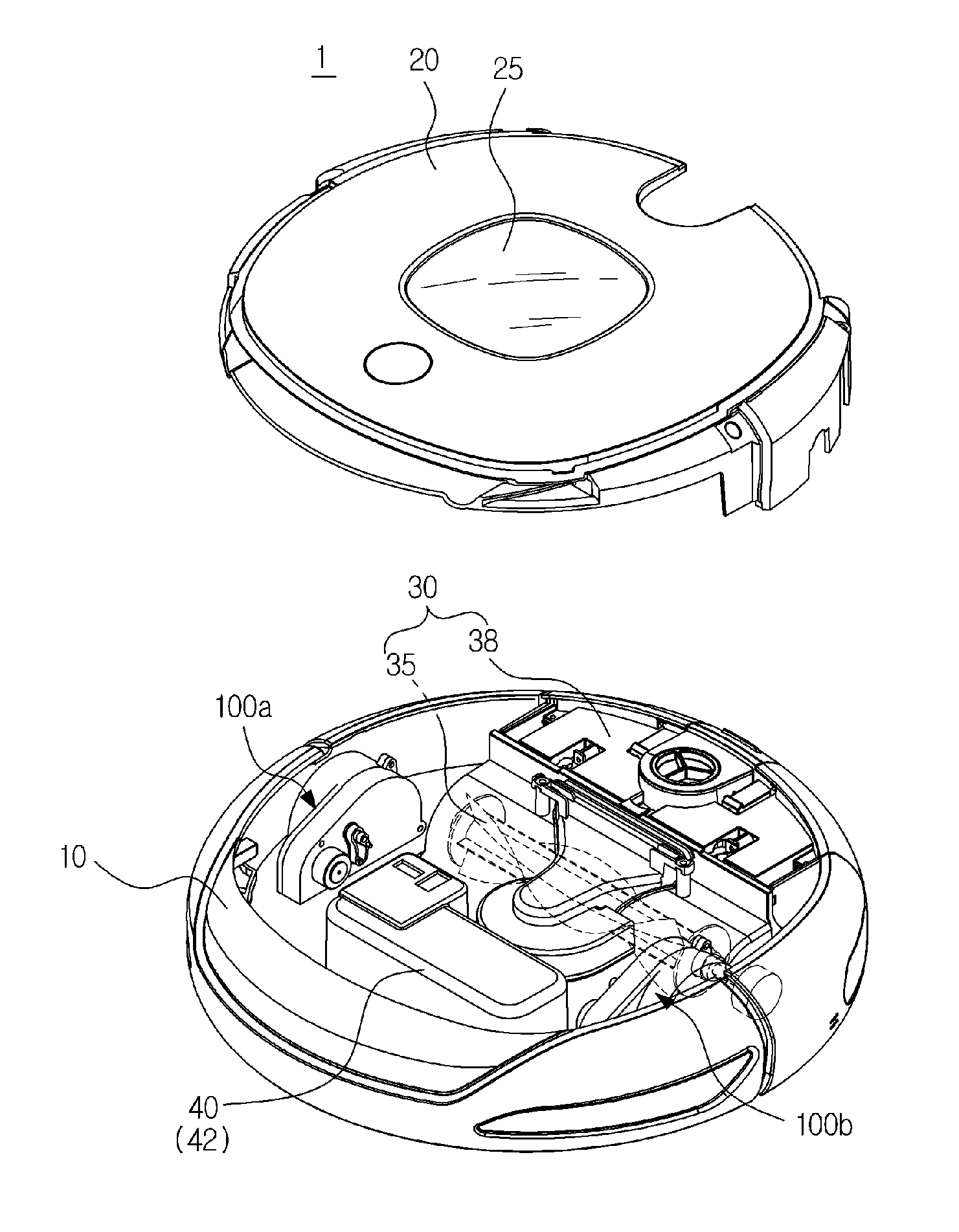
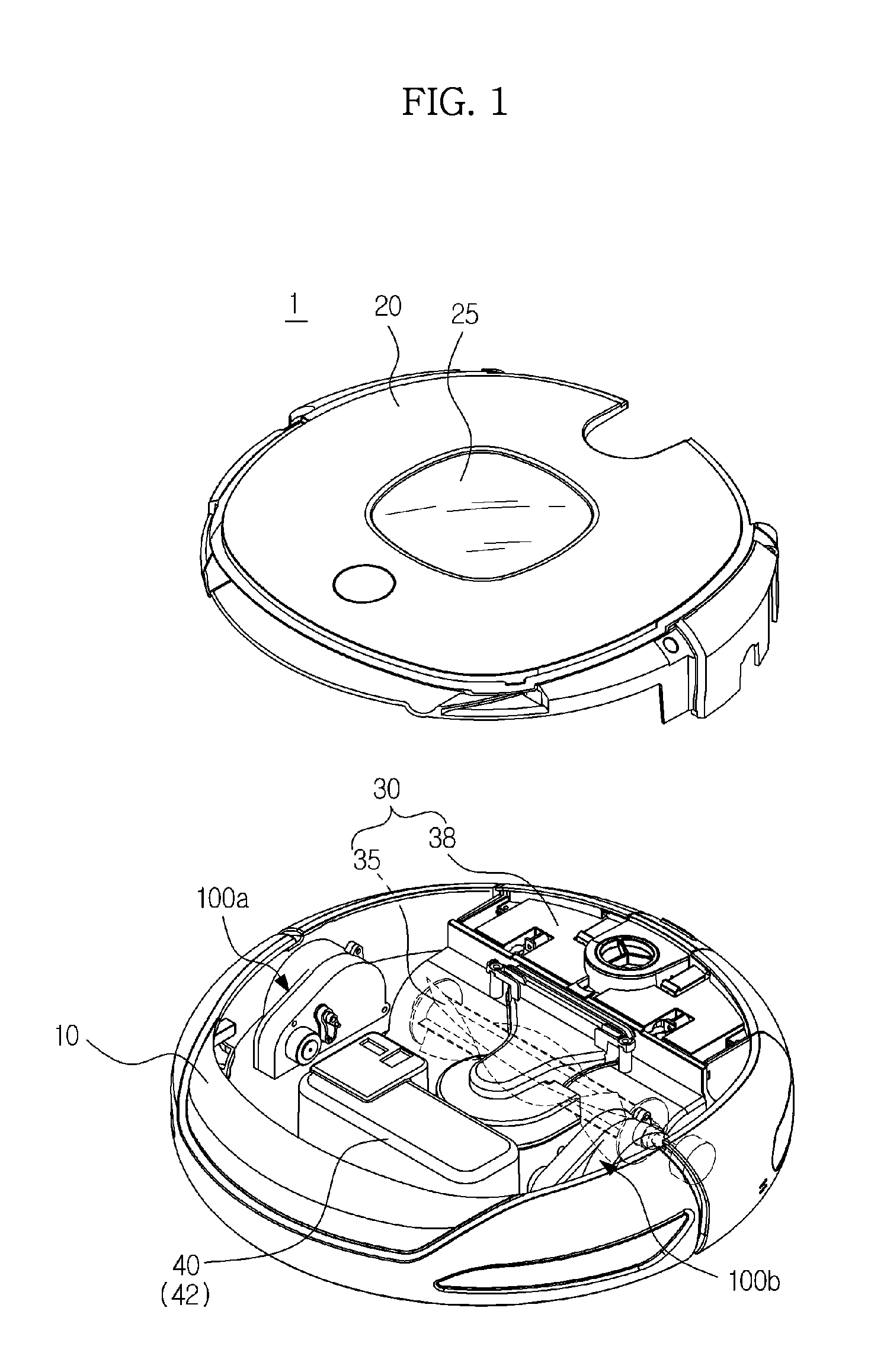
[0077]FIG. 1 is a view illustrating a structure of an autonomous cleaner in accordance with the present disclosure.

[0078]Referring to FIG. 1, the autonomous cleaner 1 may include a body 10, a cover 20 which may be configured to cover an upper portion of the body 10, a brush unit 30 which may be configured to sweep or scatter dust that exists in a cleaning area, a power unit 40 which may be configured to supply driving power for driving the body 10, and a driving wheel assembly 100A and 100B which may be configured to drive the body 10.

[0079]The body 10, while forming an exterior of the autonomous cleaner 1, may be configured to support various components which may be installed inside the body 10.

[0080]The cover 20 may include a window 25 which may be configured to transmit light generated by a camera unit (not shown) which may be configured to photograph an image toward the driving direction of the body 10.

[0081]The brush unit 30 may include a main brush 35 which may be installed at...

second embodiment

[0123]As illustrated in FIGS. 8A to 8C, a detection unit 250 which may be arranged at the driving wheel assembly 200 in accordance with the present disclosure and may be configured to detect the displacement of the driving wheel 120 may include a sensor target 252 arranged at the gear assembly 140, a guide slot 254 accommodating the sensor target 252, and a sensor 256 installed at the guide slot 254 and configured to detect the sensor target 252.

[0124]The sensor target 252 may be movably accommodated to the guide slot 254 at the lower portion of the sensor 256.

[0125]The guide slot 254 may be arranged at one side surface of a housing 210 and may accommodate the sensor target 252, and may form a driving course which guides the movement of the sensor target 252.

[0126]The sensor 256 may be installed at the upper portion of the guide slot 254 and may be configured to detect the gap distance from the sensor target 252 through the pattern change of the light received according to the gap d...

third embodiment

[0135]As illustrated in FIGS. 10A to 10C, a detection unit 350, which may be arranged at the driving wheel assembly 300 in accordance with the present disclosure and may be configured to detect the displacement of the driving wheel 120, may include a sensor target 352 arranged at the gear assembly 140, a guide slot 354 accommodating the sensor target 352, and a sensor 356 installed at the guide slot 354 and configured to detect the sensor target 352.

[0136]The sensor target 352 may be arranged in a form of a bar which may be extended from the upper portion of the gear assembly 140 toward an upward direction in approximation.

[0137]The guide slot 354 may be arranged at one side surface of a housing 310 and may accommodate the sensor target 352, and may form a driving course which may guide the movement of the sensor target 352.

[0138]The sensor 356 may be installed at the upper portion of the guide slot 354 and may be configured to detect the gap distance from the sensor target 352 thro...


PUM


Abstract

An autonomous cleaner has an enhanced structure capable of conducting an efficient cleaning task according to the material quality or the condition of the floor surface of a cleaning space.
The autonomous cleaner includes a body, a driving wheel to drive the body, a driving wheel assembly having the driving wheel, and a control unit. The control unit detects a displacement of the driving wheel corresponding to a reference position by sensing a sensor target, determines material quality or condition of a floor surface according to the displacement of the driving wheel, and controls the driving of the autonomous cleaner according to the determined material quality or the condition of the floor surface.

Description

CROSS-REFERENCE TO RELATED APPLICATION[0001]This application claims the benefit of Korean Patent Application No. 2011-0083598, filed on Aug. 22, 2011 in the Korean Intellectual Property Office, the disclosure of which is incorporated herein by reference.BACKGROUND[0002]1. Field[0003]Embodiments relate to an autonomous cleaner capable of conducting a cleaning according to material quality or condition of a floor surface, and a method of controlling thereof[0004]2. Description of the Related Art[0005]In general, an autonomous cleaner is a cleaning apparatus which automatically cleans an area intended to be cleaned without the control of a user while independently driving in the area to be cleaned by taking in foreign substances such as dust. Such an autonomous cleaner, through various sensors, etc., detects the distance to obstacles such as furniture, office equipment, or a wall within a cleaning area, and cleans the area while driving such that, by using the information detected, a c...

Claims


Application Information

Patent Timeline
Patent Type & Authority Applications(United States)
IPC IPC(8): G06F19/00
CPCA47L2201/04A47L9/2805A47L9/28B25J13/08G05D1/02
Inventor JANG, HWI CHANKIM, DONG WONJUNG, HYUN SOOHAN, SEUNG ILLEE, JUN HWA
Owner SAMSUNG ELECTRONICS CO LTD
Why Eureka
Try Eureka