Payload delivery system with forward folding stabilizer for cartridges

a cartridge and forward folding technology, applied in the field of cartridges, can solve the problems of difficult manufacturing of these components and cartridges themselves, more complex payloads that require additional complex and expensive components, and the cost of construction, tooling, and tooling, etc., and achieve the effect of precise position

Inactive Publication Date: 2013-03-07
MENEFEE III JAMES Y
View PDF9 Cites 21 Cited by
  • Summary
  • Abstract
  • Description
  • Claims
  • Application Information

AI Technical Summary

Benefits of technology

[0010]The cup-shaped stabilizer defines a cavity that can contain either the payload itself, or the cavity can contain a payload cup or container in which the payload cup or container contains the payload. For example, when the cup-shaped stabilizer is attached to the payload cup, it may be referred to as a stabilizing component or stabilizer, because it functions to impart stability and different degrees of drag to the payload cup during flight, for a desired ballistic performance. The combined and attached cup-shaped stabilizer and payload cup, which may be referred to as a “stabilized payload cup”, can provide for early or late release of the payload as desired, because stability is achieved by the function of the cup-shaped stabilizer. Additional structures and functions can be incorporated into a stabilized payload cup, such as a means to puncture or rupture a capsule that houses a gel or liquid payload contained within the stabilized payload cup.
[0011]In one aspect, the cut side wall of the cup-shaped stabilizer can be cut in a fashion such that the vanes cover substantially all the side wall area of the payload cup in the forward folded or “pre-launched” configuration, because each vane is flush against a neighboring vane. Alternatively, the cut side wall of the stabilizer can be structured such that at least some of the vanes are missing, shaped in different ways, have gaps between the vanes such that each vane is not flush against a neighboring vane, and similarly diverse configurations. Still alternatively, the cut side wall of the stabilizer can be structured such that at least some of the vanes overlap each other, which can aid in the sabot function. The common structural theme of the stabilizer is that it comprises vanes that are forward folding in their pre-launched configuration, and subsequently unfold after launching to provide a stabilizing and drag function.
[0012]When constructed of suitable materials, the cup-shaped stabilizer of this disclosure can contain the payload in its own cavity. In this aspect, the cup-shaped stabilizer function as its own type of payload container or payload cup, rather than functioning as a stabilizer, to achieve the desired performance with certain payloads, such as powders. For example, a cup-shaped stabilizer can impart a sabot effect on a projectile that it contains and be used to fire a projectile that is sub-bore diameter and to hold that projectile in a more precise position throughout launching. Also by way of example, using the cup-shaped stabilizer to contain and launch the payload itself can be useful for imposing a sudden charge of powder or liquid into a confined space, such as might be required in chemical, biological, or other encounters. When used in this fashion, the typical embodiments do not have gaps between the individual vanes such that each vane is either flush against a neighboring vane or overlaps a neighboring vane. In this manner, the barrel protection and sabot function are bolstered.

Problems solved by technology

These more complex payloads often require additional complex and expensive components beyond the nominal propellant, projectile, and primer for their effective use in cartridges.
Shotshell cartridges are also complex cartridge systems because shotshells require intricate components beyond those necessary in rifle or pistol rounds.
In all these cases, the expense and complexity of construction, tooling, and manufacture of these components and the cartridges themselves can be challenging.

Method used


Image

  • Payload delivery system with forward folding stabilizer for cartridges
  • Payload delivery system with forward folding stabilizer for cartridges
  • Payload delivery system with forward folding stabilizer for cartridges

Examples


Embodiment Construction

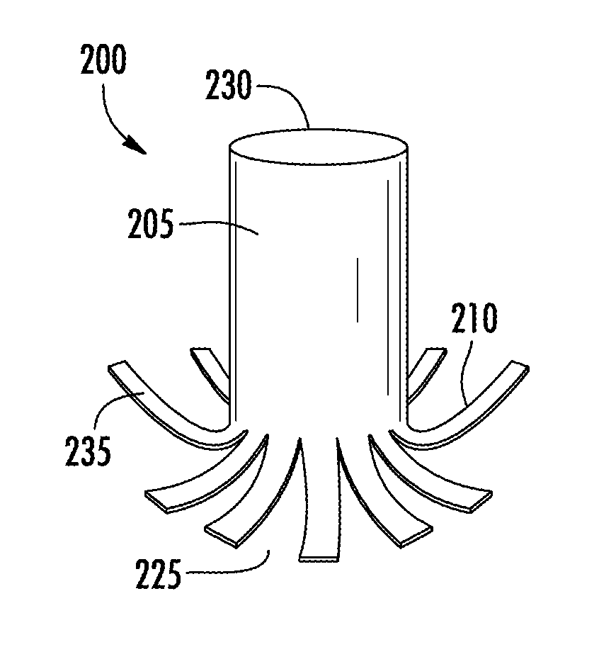
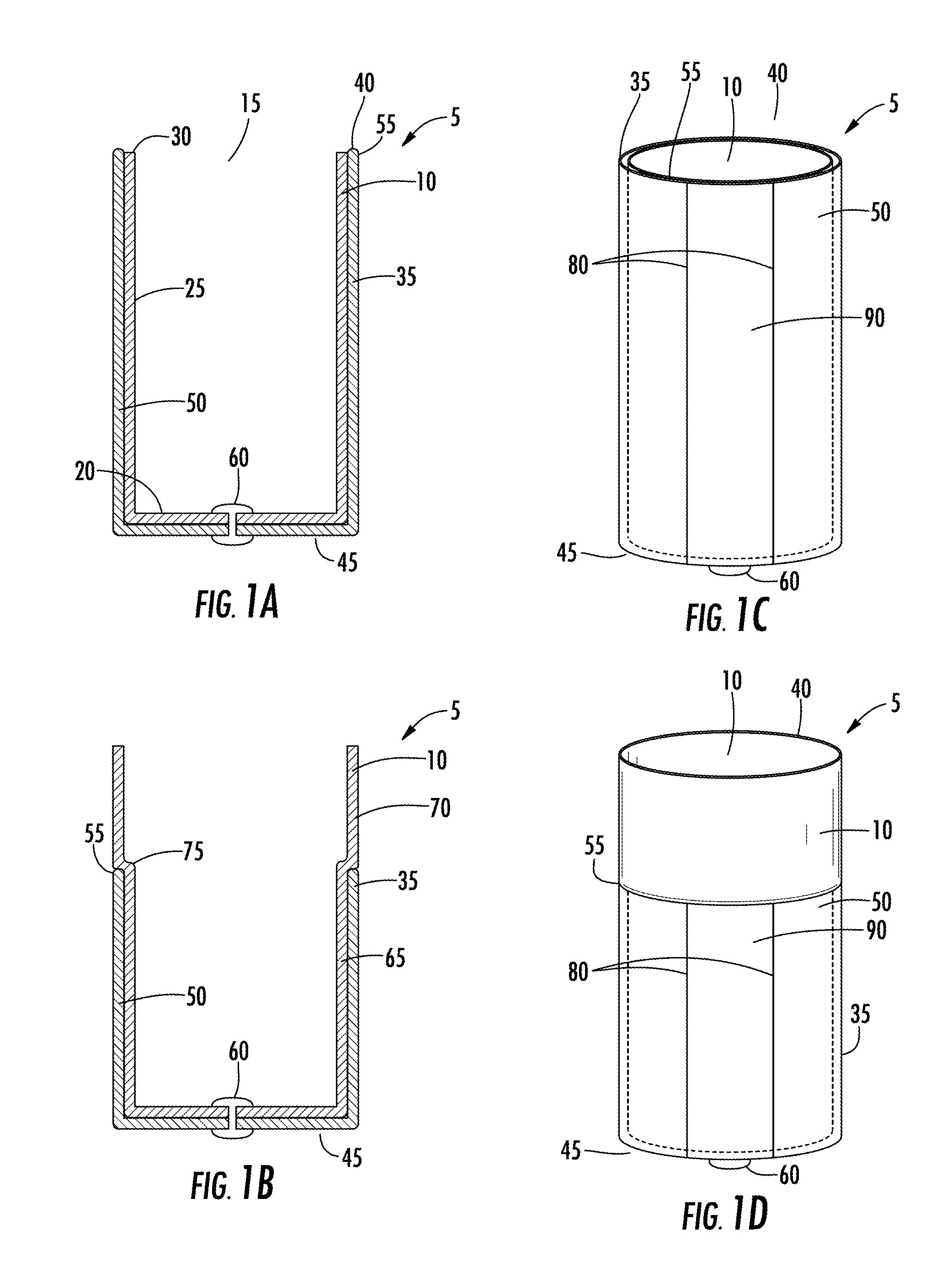
[0062]This disclosure provides for a payload delivery system for use in cartridges or launched in any fashion, the system including a cup-shaped stabilizer that assists in the discharge, launching, and ballistic performance of the payload. In some aspects, the stabilizer can serve as a flight stabilizer for any payload or payload cup to which it is attached. If desired and in some embodiments, other components such as spacers can be used along with the projectiles and the stabilizer. The cup-shaped stabilizer can be adjusted to achieve different degrees of drag for a desired ballistic performance. In other aspects, the cup-shaped stabilizer can contain the payload in its own cavity and function as its own type of payload container or payload cup. In this aspect, after a certain distance downrange, the stabilizer can open and peel back to cleanly separate from its payload. The potential advantages of this payload delivery system include using relatively low-cost components, avoiding ...


PUM


Abstract

This disclosure provides for payload delivery systems and cartridges and methods that incorporate the payload delivery systems. The payload delivery system can comprise a stabilizer having a longitudinally cut side wall defining a series of vanes that are folded forward in the pre-launched configuration. Other aspects combine a payload cup nested within the forward folding stabilizer. Still other aspects integrate the payload portion and the stabilizer portion into a single piece that constitutes a stabilized payload cup. The disclosed cartridges can be used to deliver payloads such as solid projectiles, shot of all sizes, powders, gels, liquids, and other payloads to exploit their specific function.

Description

CROSS REFERENCE TO RELATED APPLICATIONS[0001]This application claims the benefit of U.S. Provisional Application No. 61 / 530,116, filed Sep. 1, 2011, the disclosure of which is incorporated herein by reference in its entirety.TECHNICAL FIELD OF THE INVENTION[0002]This disclosure relates to cartridges for launching a payload and the cartridge components themselves, including cartridges and components for launching a payload comprising solid projectiles, liquid- or gel-containing projectiles, or powders.BACKGROUND[0003]Cartridge systems constitute extremely practical constructions and methods for deploying almost any payload or projectile downrange. Typical cartridge systems incorporate the desired payload, a propellant, and some priming composition all within a self-contained unit. While ammunition cartridges are prototypical of cartridge devices, cartridge systems have been used to launch chemical, pyrotechnic, marker, tracer, signaling, non-lethal, explosive, smoke, and other payloa...

Claims


Application Information

Patent Timeline
Patent Type & Authority Applications(United States)
IPC IPC(8): F42B12/00F42B14/00F42B10/06F42B12/42F42B12/40F42B12/38F42B12/02F42B12/20F42B12/22F42B12/46F42B7/04F42B12/04F42B10/02F42B12/44
CPCF42B7/08F42B12/76
Inventor MENEFEE, III, JAMES Y.
Owner MENEFEE III JAMES Y
Why Eureka
Try Eureka