
Hybrid valve for attenuation of low frequency noise

Active Publication Date: 2013-03-07
FAURECIA EMISSIONS CONTROL TECH GERMANY
View PDF5 Cites 20 Cited by
  • Summary
  • Abstract
  • Description
  • Claims
  • Application Information

AI Technical Summary

Benefits of technology

This patent describes a hybrid valve assembly for an exhaust system that can control the movement of a vane to regulate the flow of exhaust gas. The valve has a resilient member that controls the vane's position, and a valve actuator that can be actively or passively controlled to move the vane. The assembly provides a wide range of control over the exhaust flow path and can adapt to changes in exhaust gas pressure. The method for controlling the valve enables users to select between an ON and OFF position based on their desired valve characteristic. Overall, this invention allows for more precise and efficient control of exhaust gas flow in an exhaust system.

Problems solved by technology

Although effective, mufflers are often relatively large in size and provide limited nose attenuation.
However, the proposed valves have numerous drawbacks that limit their widespread use in a variety of applications.
The spring has limited application in high temperature environments.
Special high-temperature spring materials are often required, which can be very expensive.
Also, these valves can be difficult to package in smaller sized mufflers, which are typically used as part of a multi-muffler configuration for larger vehicles such as trucks, SUVs, mini-vans, etc.
Providing by-pass flow paths is disadvantageous from an assembly, material, and weight perspective.
Further, as discussed above, it is difficult to package these valves in smaller mufflers, and these valves are not able to operate effectively in high temperature environments.
Additionally, these known passive valve configurations do not effectively attenuate low frequency noise.
Increasing muffler volume is disadvantageous from a cost, material, and packaging space perspective.
Increasing backpressure can adversely affect engine power.
However, this is disadvantageous from a cost and packaging perspective.

Method used


Image

  • Hybrid valve for attenuation of low frequency noise
  • Hybrid valve for attenuation of low frequency noise
  • Hybrid valve for attenuation of low frequency noise

Examples


Embodiment Construction

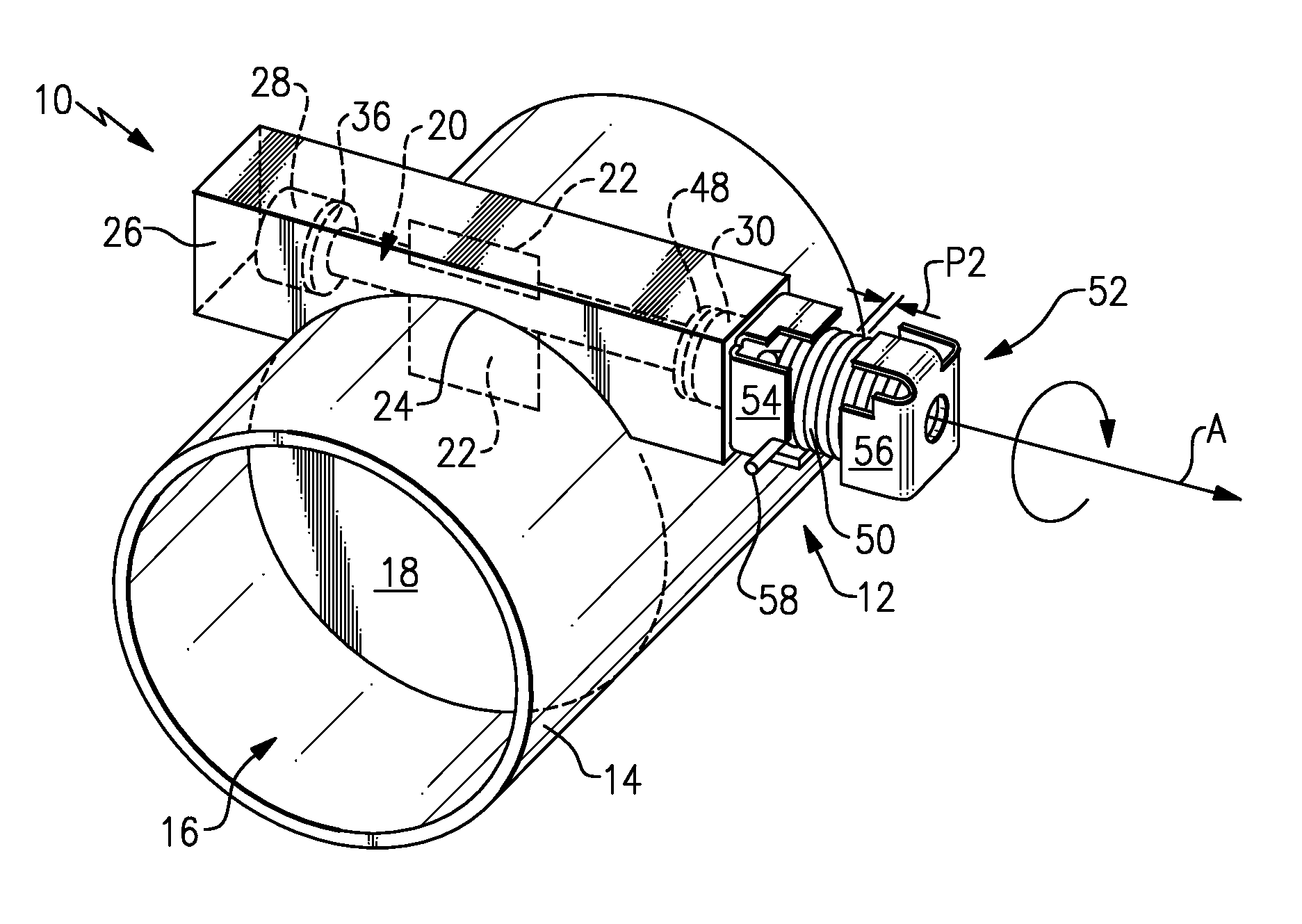
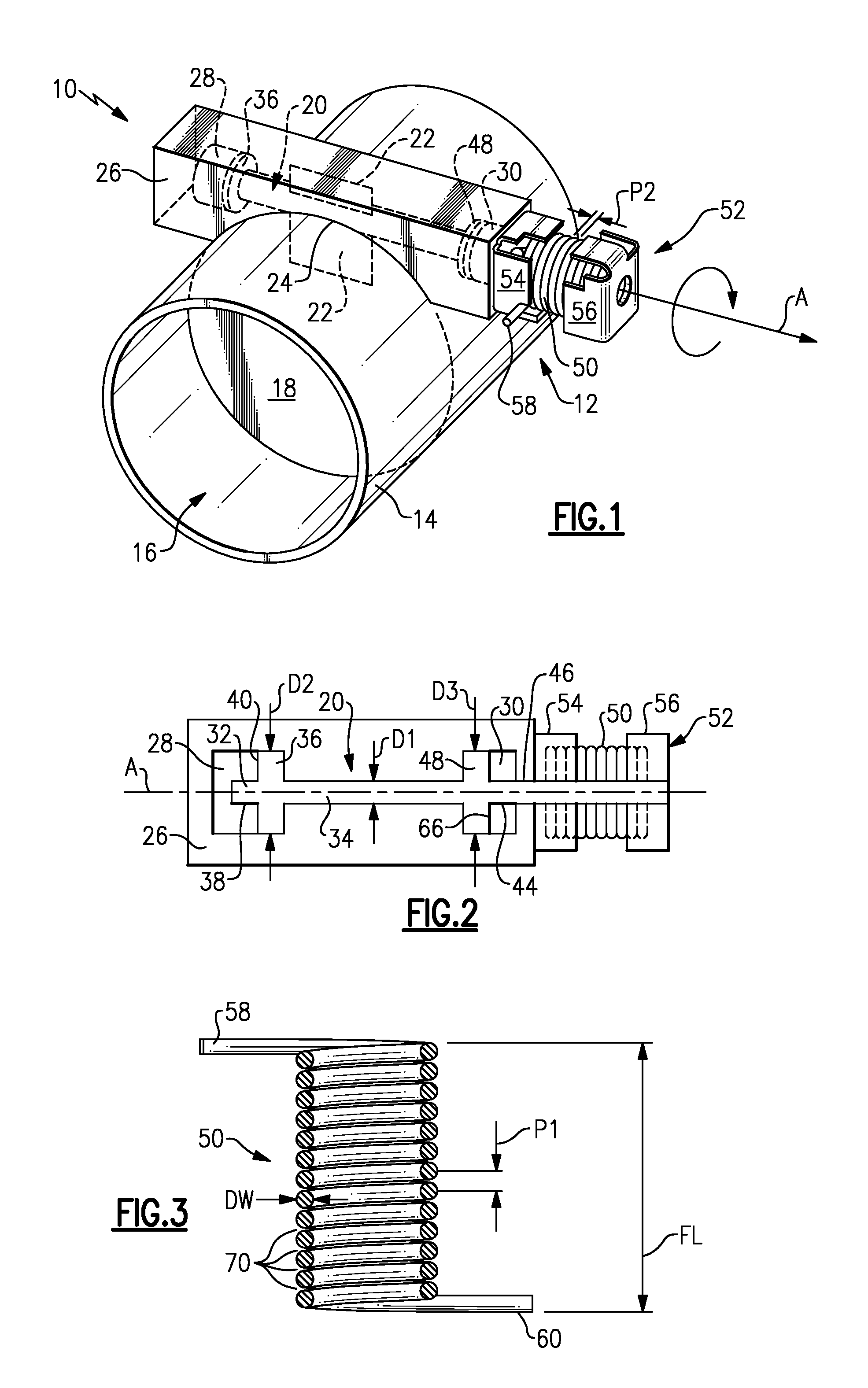
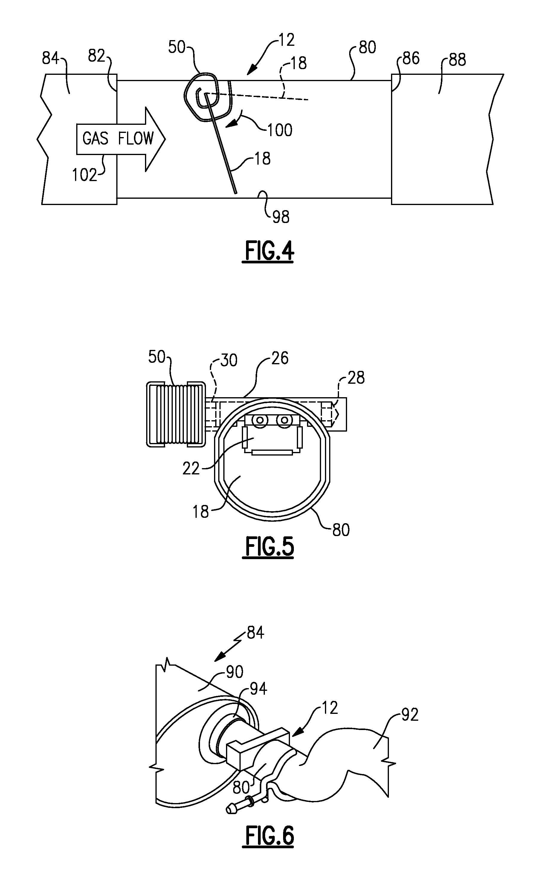
[0030]An exhaust component 10 (FIG. 1) includes an exhaust valve, referred to as a passive valve assembly 12, which is movable between an open position and a closed position. In the example shown, the exhaust component 10 comprises a tube body 14 that defines an exhaust gas flow path 16 having a specified cross-sectional area. The passive valve assembly 12 includes a valve body or vane 18 that blocks a portion of the exhaust gas flow path 16 when in the closed position. The vane 18 is pivoted toward the open position to minimize blockage of the exhaust gas flow path 16 in response to pressure exerted against the vane 18 by exhaust gases.

[0031]In one example the vane 18 is fixed to a shaft 20 with a tang or bracket 22. A slot 24 is formed within an outer surface of the tube body 14. A housing 26, shown in this example as a square metal structure, is received within this slot 24 and is welded to the tube body 14. Other housing configurations could also be used. The shaft 20 is rotatab...


PUM


Abstract

A hybrid valve assembly for an exhaust system includes an exhaust tube having a bore defining an exhaust flow path. A vane is mounted within the bore and is moveable between an open position and a closed position. A resilient member biases the vane toward the closed position. A valve actuator has an ON position where movement of the vane is actively controlled by the valve actuator and an OFF position where movement of the vane is passively controlled by exhaust gas flow.

Description

RELATED APPLICATIONS[0001]This application is a continuation-in-part of application Ser. No. 11 / 950,034, filed on Dec. 4, 2007, which is a continuation-in-part of application Ser. No. 11 / 692,964 filed on Mar. 29, 2007, now U.S. Pat. No. 7,748,404, and claims priority to provisional application No. 60 / 989,508 filed on Nov. 21, 2007.TECHNICAL FIELD[0002]The subject invention relates to a hybrid valve assembly in a vehicle exhaust system, and more particularly to a hybrid valve assembly that selectively provides a passive valve function or an actively controlled function to provide a desired valve characteristic.BACKGROUND OF THE INVENTION[0003]Exhaust systems are widely known and used with combustion engines. Typically, an exhaust system includes exhaust tubes that convey hot exhaust gases from the engine to other exhaust system components, such as mufflers, resonators, etc. A muffler includes acoustic chambers that cancel out sound waves carried by the exhaust gases. Although effecti...

Claims


Application Information

Patent Timeline
IPC IPC(8): F16K15/00
CPCF01N1/08F01N1/165F01N13/085F01N2240/36F01N2410/00F02D9/04F02D9/103F16K15/033Y10T137/0324Y10T137/7898
Inventor ABRAM, KWINCALLAHAN, JOSEPHWILLATS, ROBIN
Owner FAURECIA EMISSIONS CONTROL TECH GERMANY
Learn More