
Device for measuring the speed of displacement of an object deforming the lines of the terrestrial magnetic field

Inactive Publication Date: 2013-03-07
COMMISSARIAT A LENERGIE ATOMIQUE ET AUX ENERGIES ALTERNATIVES
View PDF16 Cites 9 Cited by
  • Summary
  • Abstract
  • Description
  • Claims
  • Application Information

AI Technical Summary

Benefits of technology

The invention is a device for measuring the speed of movement of a ferromagnetic object, such as an automobile vehicle, using magnetic fields. The device includes two magnetometers placed on either side of a traffic roadway, which measure the changes in the magnetic field caused by the movement of the object. A processing unit calculates the speed of the object based on the measurements and the installation position of the magnetometers. Additionally, the device can also detect the distance between objects and identify the type of object based on its unique magnetic signature. The technical effects of this invention include improved traffic control and safety by providing accurate data on the speed and distance between objects, as well as the identification of specific objects. The device can be installed in road signs or signs embedded in the road surface.

Problems solved by technology

The measurement of the speed of vehicles is an on-going issue for ensuring road safety.
These installations which allow a precise measurement of the speed to be made are very costly and complex.
However, an operator has to aim at the vehicle and the driver at fault has to be apprehended shortly following his infraction.
However, the precision of the measurement is not optimum and the cost of installation of an inductive loop into the roadway is a significant intervention and very costly.
Furthermore, these loops integrated into the roadway are subjected to large stresses, in particular by heavy trucks, reducing their lifetimes.
Although the price of these sensors is affordable, these installations suffer from a lack of precision, such that their use, notably in urban areas requiring a more precise speed measurement, is not appropriate.
However, this solution described with military vehicles is not adapted to a situation for monitoring traffic where the vehicles can closely follow one another.

Method used


Image

  • Device for measuring the speed of displacement of an object deforming the lines of the terrestrial magnetic field
  • Device for measuring the speed of displacement of an object deforming the lines of the terrestrial magnetic field
  • Device for measuring the speed of displacement of an object deforming the lines of the terrestrial magnetic field

Examples


Embodiment Construction

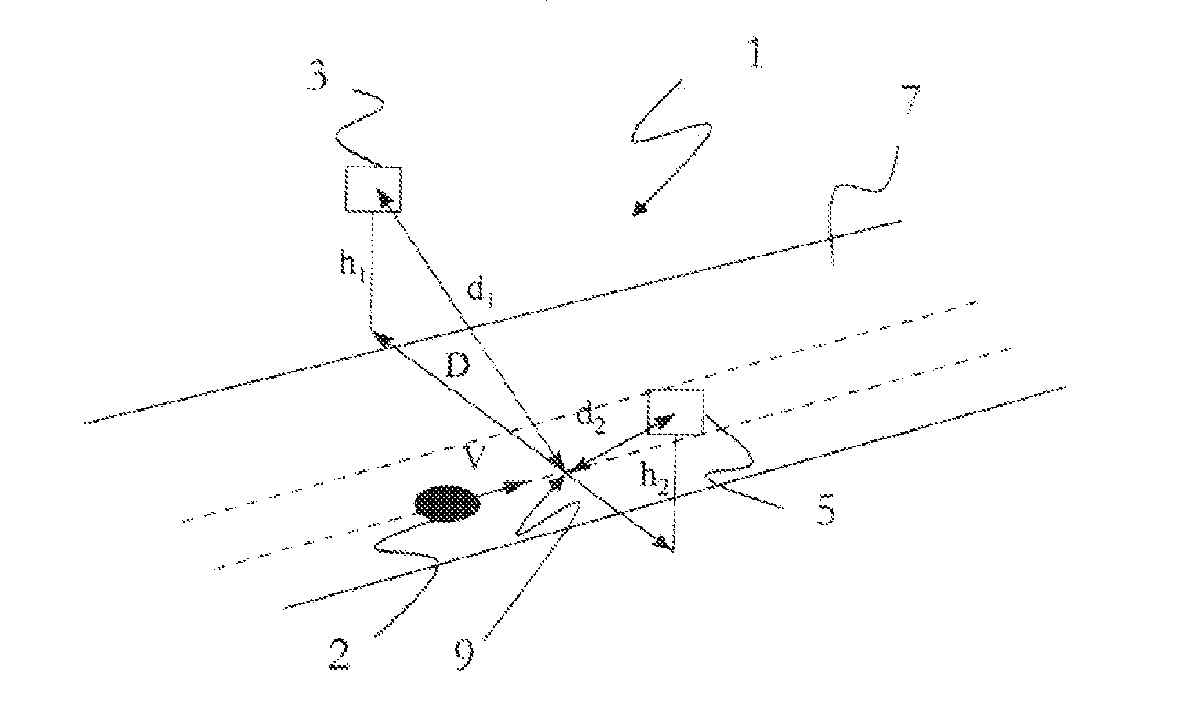
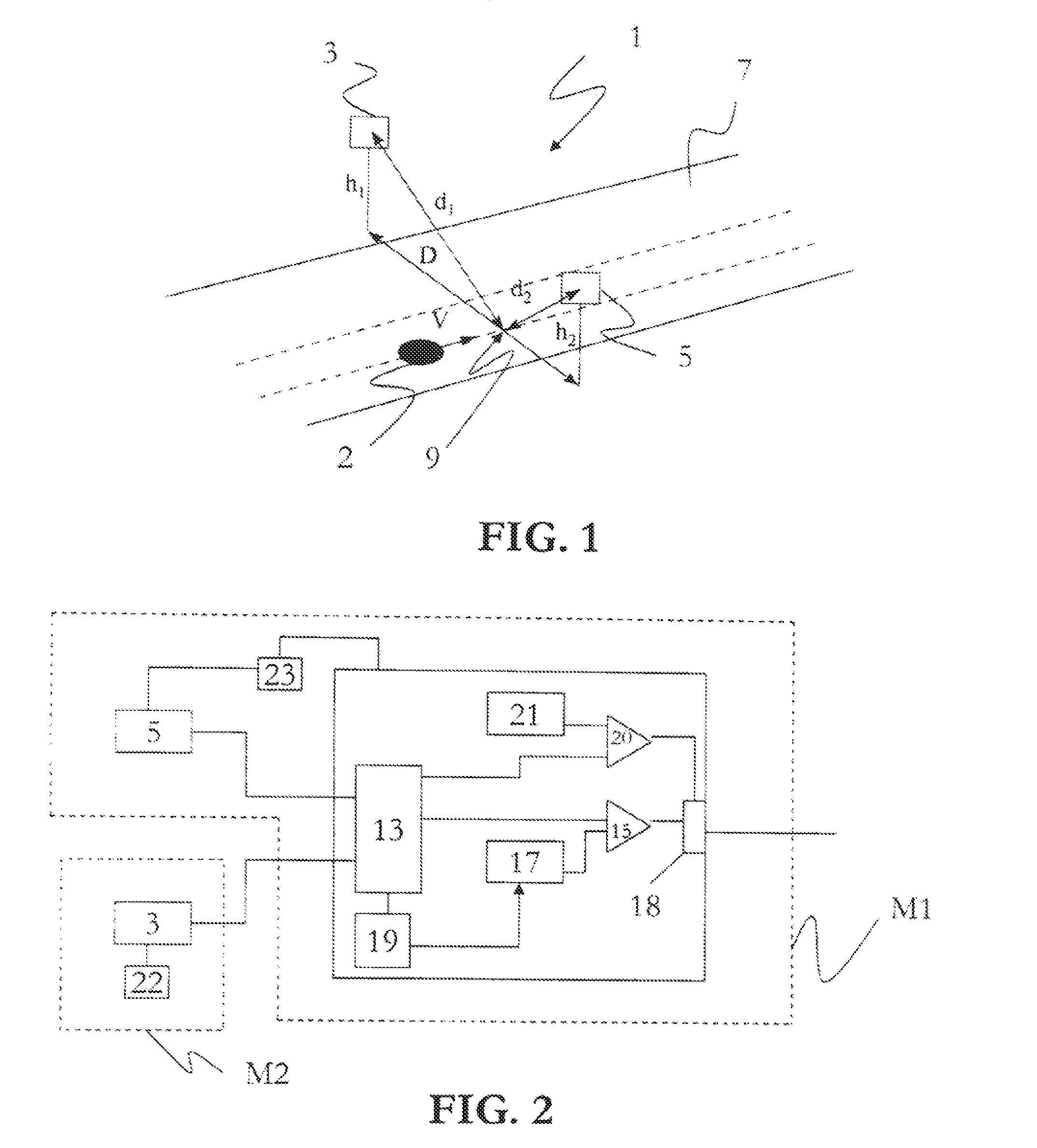
[0032]In these figures, identical elements carry the same references.

[0033]FIG. 1 illustrates a device 1 for measuring the speed of movement of an object 2 deforming the lines of the Earth's magnetic field, such as a ferromagnetic object such as an automobile vehicle. It could also be an object that is non-ferromagnetic, but carrying a magnet, an electromagnet or an AC magnetic field generator.

[0034]Automobile vehicle is understood to include, together with cars or trucks, both trains or aircraft, moving for example at an airport over a taxiway or runway.

[0035]This device comprises at least a first 3 and second 5 magnetometer disposed on either side of a traffic roadway 7 for said object and substantially perpendicular to the latter.

[0036]By design, the magnetometers 3 and 5 are configured for measuring the deformation of the Earth's magnetic field upon passage of said object moving over said roadway, in other words upon passage of a vehicle.

[0037]The traffic roadway 7 is, in the pr...


PUM


Abstract

An apparatus for measuring speed of movement of an object deforming lines of Earth's magnetic field includes a first and second magnetometer disposed on either side of a traffic roadway for the object and substantially perpendicular to the object. The magnetometers are configured for measuring deformation of Earth's magnetic field by the object travelling over the roadway. The apparatus also includes a processing unit configured for extracting, from each of the magnetometers, a measurement value corresponding to a quotient defined by a distance of the object with respect to the magnetometer divided by a speed of movement of the object, and for calculating a speed of the object from the measurement values and a geometrical disposition of the magnetometers with respect to one another and with respect to the traffic roadway.

Description

TECHNICAL FIELD[0001]The invention relates to a device for measuring the speed of movement of an object deforming the lines of the Earth's magnetic field.BACKGROUND ART[0002]The measurement of the speed of vehicles is an on-going issue for ensuring road safety. Thus, studies have demonstrated that the number of road accidents is directly correlated with the average speed of the vehicles.[0003]At the present time, several devices exist for measuring the speed of automobile vehicles:[0004]For example, fixed or mobile radar devices are noted. These installations which allow a precise measurement of the speed to be made are very costly and complex.[0005]Laser sighting devices use the Doppler effect for the speed measurement and also allow a precise measurement of the speed of vehicles. However, an operator has to aim at the vehicle and the driver at fault has to be apprehended shortly following his infraction.[0006]Furthermore, inductive loops installed under the roadway also exist. How...

Claims


Application Information

Patent Timeline
IPC IPC(8): G01B7/14
CPCG01P3/42G08G1/052G08G1/042G01P3/66G01P3/803
Inventor ROBINET, ANTOINEBLANPAIN, ROLAND
Owner COMMISSARIAT A LENERGIE ATOMIQUE ET AUX ENERGIES ALTERNATIVES
Learn More