

Imaging element and imaging apparatus
a technology of imaging apparatus and element, applied in the direction of color signal processing circuit, television system scanning details, television system, etc., can solve the problem of not being able to control the green component according to the brightness level
- Summary
- Abstract
- Description
- Claims
- Application Information
AI Technical Summary
Benefits of technology
Problems solved by technology
Method used
Image

Examples
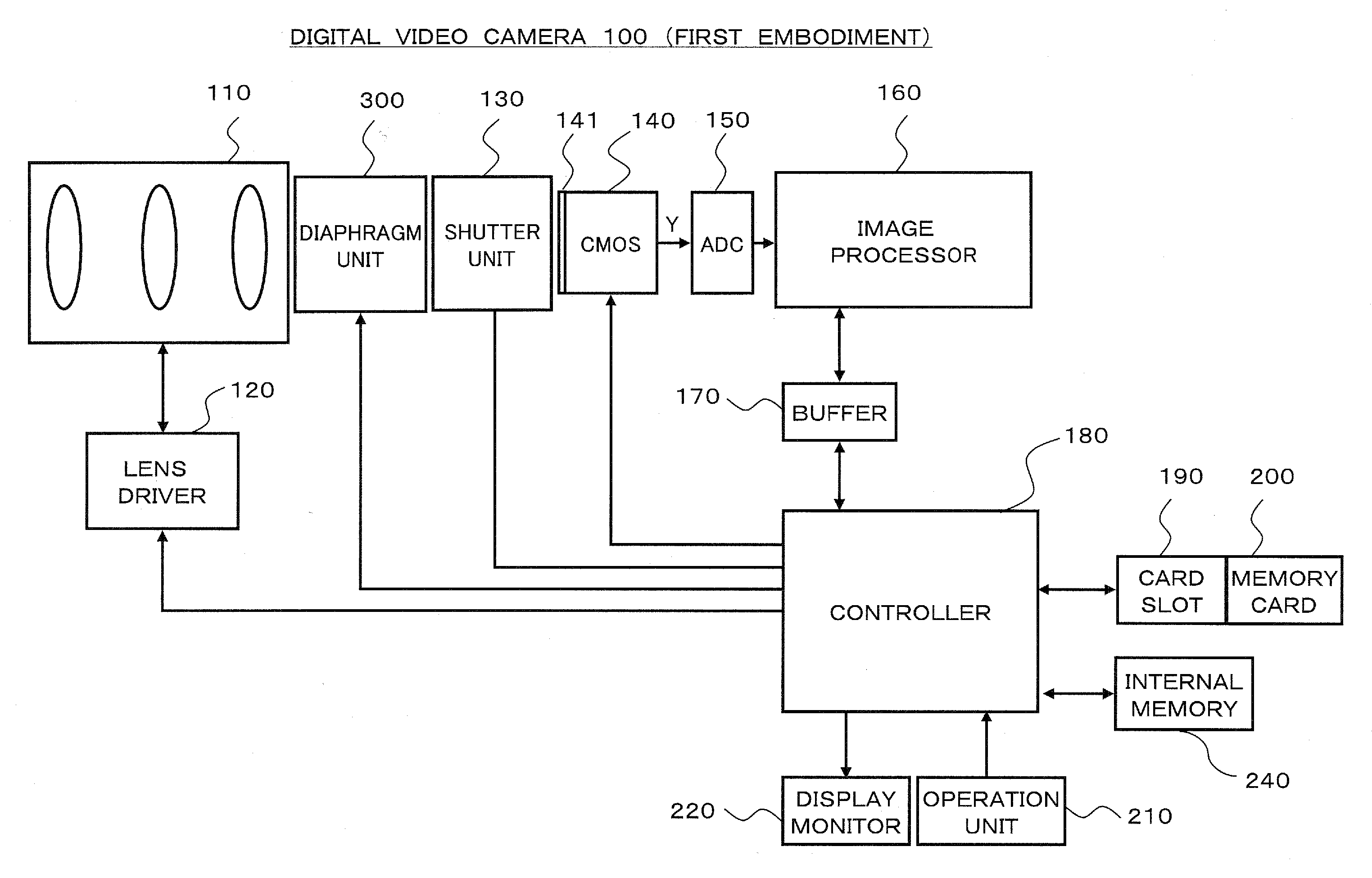
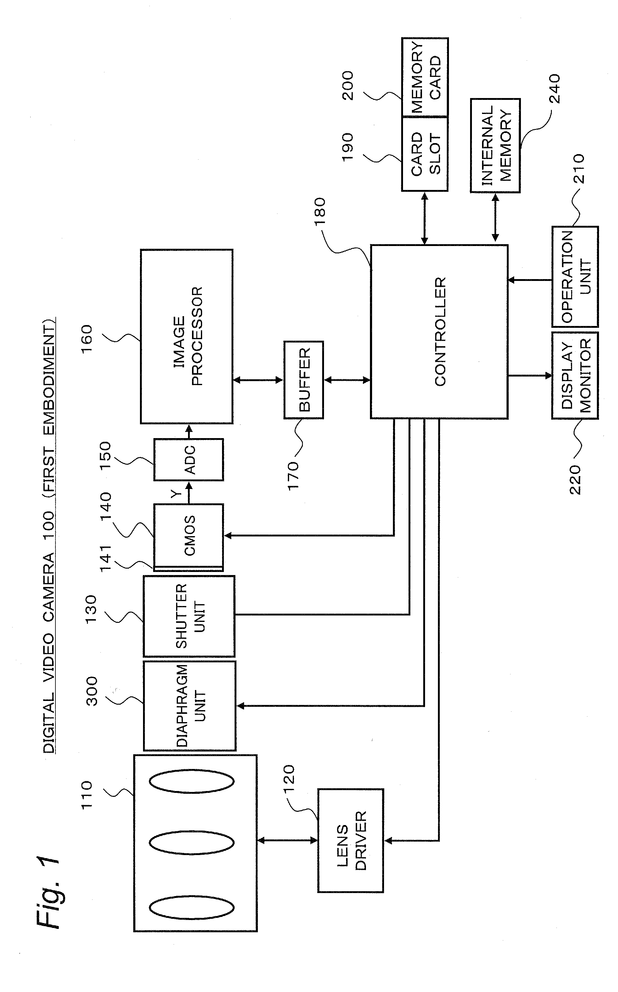
first embodiment
Spectral Sensitivity of Color Filter (First Embodiment)
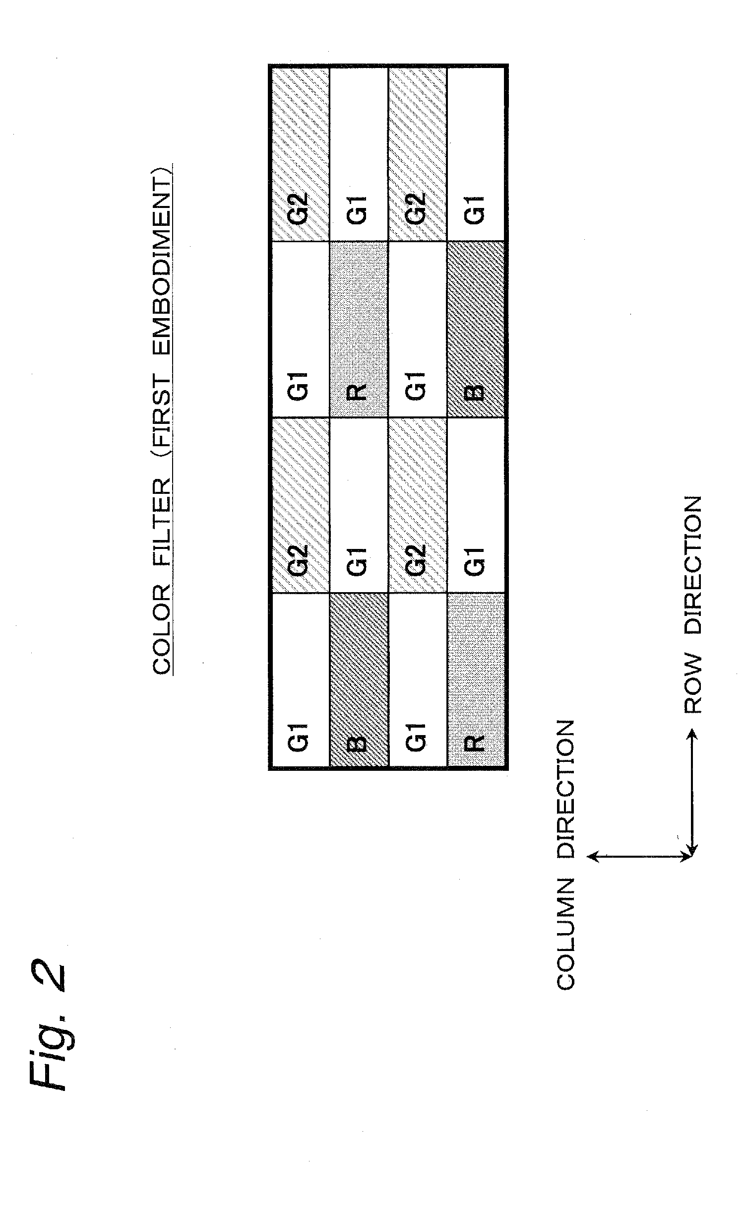
[0047]Here, the spectral sensitivity of each color filter is as shown in FIG. 3. More specifically, the blue color filter (B) has a peak (maximum value) of the spectral sensitivity in a neighborhood of a short wavelength of 400 nm. The red color filter (R) has a peak (maximum value) of the spectral sensitivity in a neighborhood of a long wavelength of 600 nm. The one color filter (G1) of the two kinds of green color filters with different spectral sensitivity has a peak (maximum value) P1 of the spectral sensitivity in a neighborhood of 550 nm. The other color filter (G2) of the two kinds of green color filters of different spectral sensitivity has a peak (maximum value) P2 of the spectral sensitivity in a neighborhood of 500 nm. Although in this embodiment, the peak of the spectral sensitivity of the one color filter (G1) is set to 550 nm, it may be set to a value shifted from 550 nm in the range of ±20 nm. In addition, althoug...
PUM
 Abstract
Description
Claims
Application Information