Device and method for determining the position of a working part

a technology for working parts and devices, applied in the field of devices and methods for determining the position of working parts, can solve the problems of reducing accuracy and reliability, slow method, and detectors or detectors are extremely exposed to damage during working, etc., and achieve the effect of convenient us

Inactive Publication Date: 2006-02-21
TRIMBLE INC
View PDF56 Cites 39 Cited by
  • Summary
  • Abstract
  • Description
  • Claims
  • Application Information

AI Technical Summary

Benefits of technology

[0013]One object of the invention is to provide a control indication for a ground-preparing machine, which makes possible adequate control of the machine with so few as possible measuring units placed outside the machine.
[0016]Yet another object of the invention is to provide great flexibility in the setting up of a measuring system in relation to the working machine in combination with large work regions, high accuracy and distance and / or close indicatable positioning.
[0021]The position- and orientation-determining apparatus can comprise, on one hand, a relatively slow, accurate determining device, which at time intervals accurately measures the current position and orientation of the machine, and on the other hand a fast determining device, which reacts on position and / or orientation changes in order to calculate and update the calculation between said time intervals. This fast determination device in this case only has to be stable for short periods of time because a slow drift is corrected through update from the slower device.
[0027]As it is the position and orientation of the working machine itself which are measured, and as the position of the working part is then calculated with the help of signals from the positional relationship devices, a system is obtained which can use separate control and sensor systems of any type for the machine, especially concerning preparation machines and excavators. Sensitive rotation indicators on the vibration-working part itself can be avoided.

Problems solved by technology

This arrangement with the position sensor on the machine and the height sensor on the blade does not solve the problem of determining the position of the blade in a fixed coordinate system, which is also pointed out in U.S. Pat. No. 5,612,864 (Caterpillar Inc).
The detector or detectors are sometimes obscured by the machine if they are not placed on high masts, which reduces the accuracy and reliability.
The detector or detectors are extremely exposed to damage during working, dirt, vibrations, mechanical damage, etc.
To determine the orientation and inclination via machine movements is furthermore a slow method and it is not unambiguous if the machine can reverse or move side-ways.
Likewise, position- and height-determination with the aid of GPS-technique or with electronic angular and distance measuring often is not sufficiently fast in order to be able to measure the position and, above all, the height with sufficient accuracy during fast displacements.

Method used


Image

  • Device and method for determining the position of a working part
  • Device and method for determining the position of a working part
  • Device and method for determining the position of a working part

Examples


embodiment 1

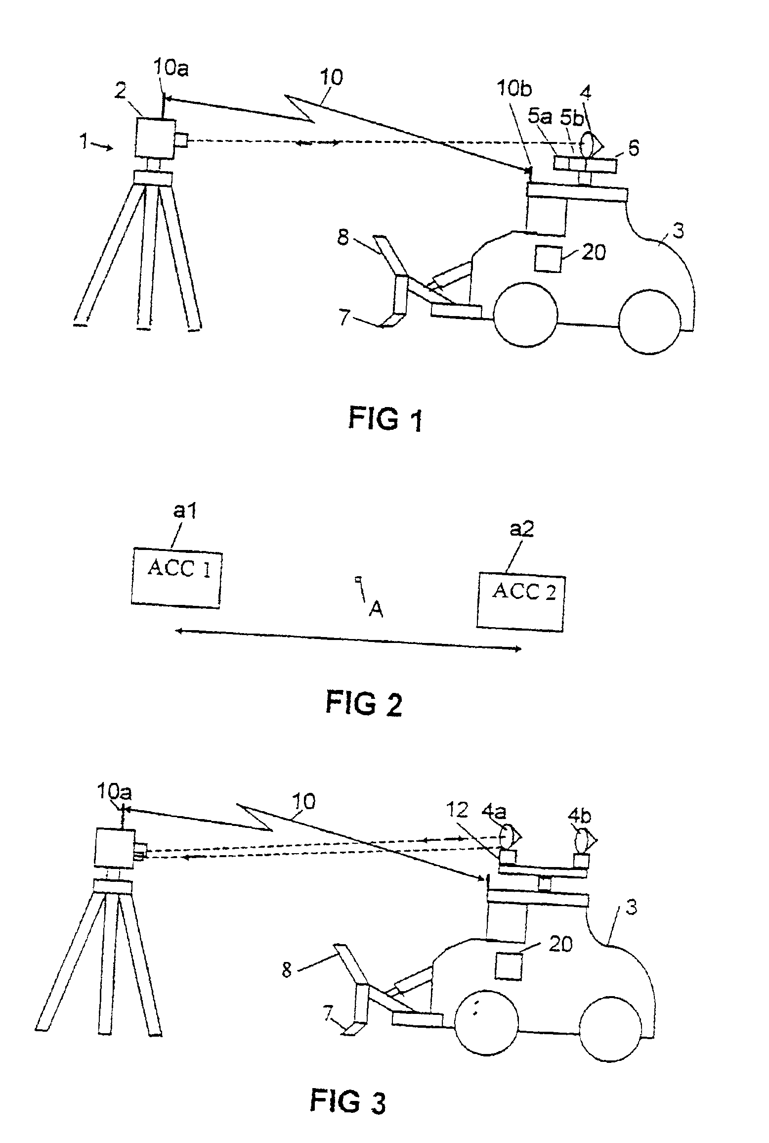
[0039]According to the embodiment shown in FIG. 1, a geodesic instrument I is set up on a ground area which is to be treated. The instrument 1 is, for example, an electronic distance-measuring instrument 2 with an integrated distance and angular measurement of the type which is called a total station and which is marketed by SPECTRA PRECISION AB, i.e. with combined advanced electronic and computer techniques. The position and the horizontal angular position of the instrument 1 is first measured in the common way well-known for the skilled man. This can, for example, be performed through measuring against points in the region with predetermined positions, e.g. church towers or the like.

[0040]A geodesic instrument gives both the distance as well as the vertical and horizontal direction towards a target, whereby the distance is measured against a reflector, e.g. of the corner cube type. A geodesic instrument is furthermore provided with a computer with writeable information for measuri...

embodiment 2

[0051]The ground-preparation machine 3 in FIG. 3 is, for the slow, accurate orientation determination around the vertical axis, in this embodiment provided with two reflector units 4a and 4b in a placement on the machine which is easily visible from the geodesic instrument 1. In the embodiment according to FIG. 3 they are placed with an essentially fixed placement in relation to each other and the machine. The possibility of having the reflectors movable between different “fixed” positions, in order to obtain a suitable orientation in relation to the measuring instrument, is obvious. Each of them should preferably consist of a set of corner cube prisms placed in circle around an axis.

[0052]The machine's three-dimensional placement and orientation in a fixed, or in relation to the measuring instrument defined coordinate system is measured through the measurement towards the reflector units 4a and 4b, which have a precise or determinable placement in the coordinate system of the machi...

embodiment 3

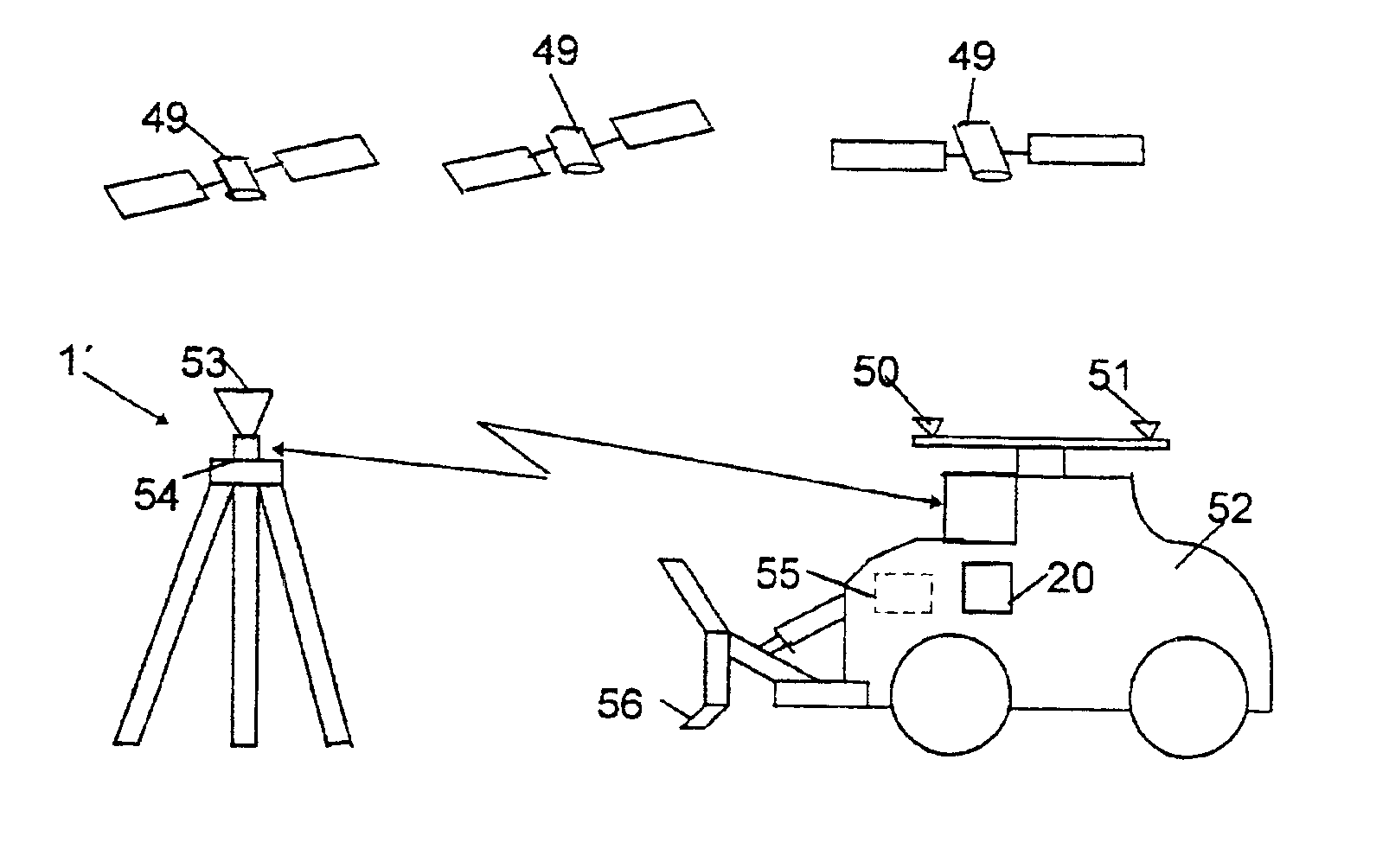
[0066]In the above-described embodiments the position measuring has occurred through measuring against one or more targets on the measuring object from a geodesic instrument 1. Position-measuring can also occur with the help of radio navigation, e.g. GPS (Global Position System), by placing one or more radio navigation antennae on the measuring object and one on a stationary station to one side.

[0067]In the embodiment shown in FIG. 6 there is a radio navigation antenna 50, which here is shown receiving signals from a number of GPS-satellites 49, at the periphery of a rotating disc 51 on the upper part of an excavator 52. The position of the antenna is indicated in a radio navigation receiver 55 in at least two predetermined rotational positions of the disc 51 in relation to the excavator 52. The disc rotates so slowly that the antenna position in each rotational position can be indicated with accuracy but still so fast that normal movements of the excavator do not significantly infl...


PUM


Abstract

The invention relates to a device and to a method for determining the position for a working part of a tool on a working machine with a position-determining apparatus (2, 4, 5, 6; 2, 4a, 4b, 5, 6′; 31, 33, 49, 50, 51, 1′,53). At least one detector equipment (4, 5, 6; 4a, 4b, 5, 6′; 31, 33; 49, 50, 51, 53) is placed at a defined place on the working machine (3; 52) in order to determine the position of this position in a fixed coordinate system. At least one positional relationship device (11) determines the positional relation of the working part in relation to the detector equipment in a machine-based coordinate system. A calculating device (20) calculates, with signals from the position-determining apparatus and the positional relationship device, the position of the working part in the fixed coordinate system. The position-determining apparatus comprises an inclination- and orientation-measuring device (5, 20; 4a, 4b, 20; 31, 20; 51, 20) so that the apparatus measures both the instantaneous position and orientation of said position of the working machine in the fixed coordinate system. The calculating device (20) converts the measuring result from the position-determining apparatus and the positional relationship device in order to give the instantaneous position and / or orientation of the working part in the fixed coordinate system.

Description

[0001]The present invention relates generally to devices for determining the position of a working part of a tool on a working machine with a position-determining apparatus, and methods for determining the position of a working part of a tool on a working machine. The invention concerns particularly the controlling of an industrial machine, for example a ground-leveling machine, crane, dredger or the like.BACKGROUND OF THE INVENTION[0002]During road construction or the leveling of ground, for example for buildings, parks or playgrounds, vehicle displays or the like, ground preparation machines are used which are to give a predetermined topography to the place of ground through, on one hand digging and on the other hand piling up material.[0003]It is important in this connection that the working tools on the machines that are used can be accurately controlled to the exact right working level in the intended section. The control should preferably even be able to be remote-controlled a...

Claims


Application Information

Patent Timeline
Patent Type & Authority Patents(United States)
IPC IPC(8): G06F7/00G01C21/00G06F17/00E02F3/84E02F9/20G01C15/00G01S5/14
CPCE02F3/842E02F9/2045E02F3/847
Inventor ERICSSON, LARSHERTZMAN, MIKAEL
Owner TRIMBLE INC
Why Eureka
Try Eureka