Laser type engine ignition device

Active Publication Date: 2006-11-02
DENSO CORP +1
View PDF16 Cites 39 Cited by
  • Summary
  • Abstract
  • Description
  • Claims
  • Application Information

AI Technical Summary

Benefits of technology

[0008] Therefore, an object of the invention is to provide an improved laser type engine ignition device that can sufficiently control

Problems solved by technology

Although it is necessary to properly control laser oscillation in order to secure complete ignition and a sufficient combustion speed, a conventional laser type ignition device, such as disclosed in JP-A-10-196471, can not sufficiently control laser oscillation, so that a complete ignition or a combustion speed can not be

Method used


Image

  • Laser type engine ignition device
  • Laser type engine ignition device
  • Laser type engine ignition device

Examples


first embodiment

[0033] A laser type ignition device 100 according to the invention will be described with reference to FIGS. 1-6.

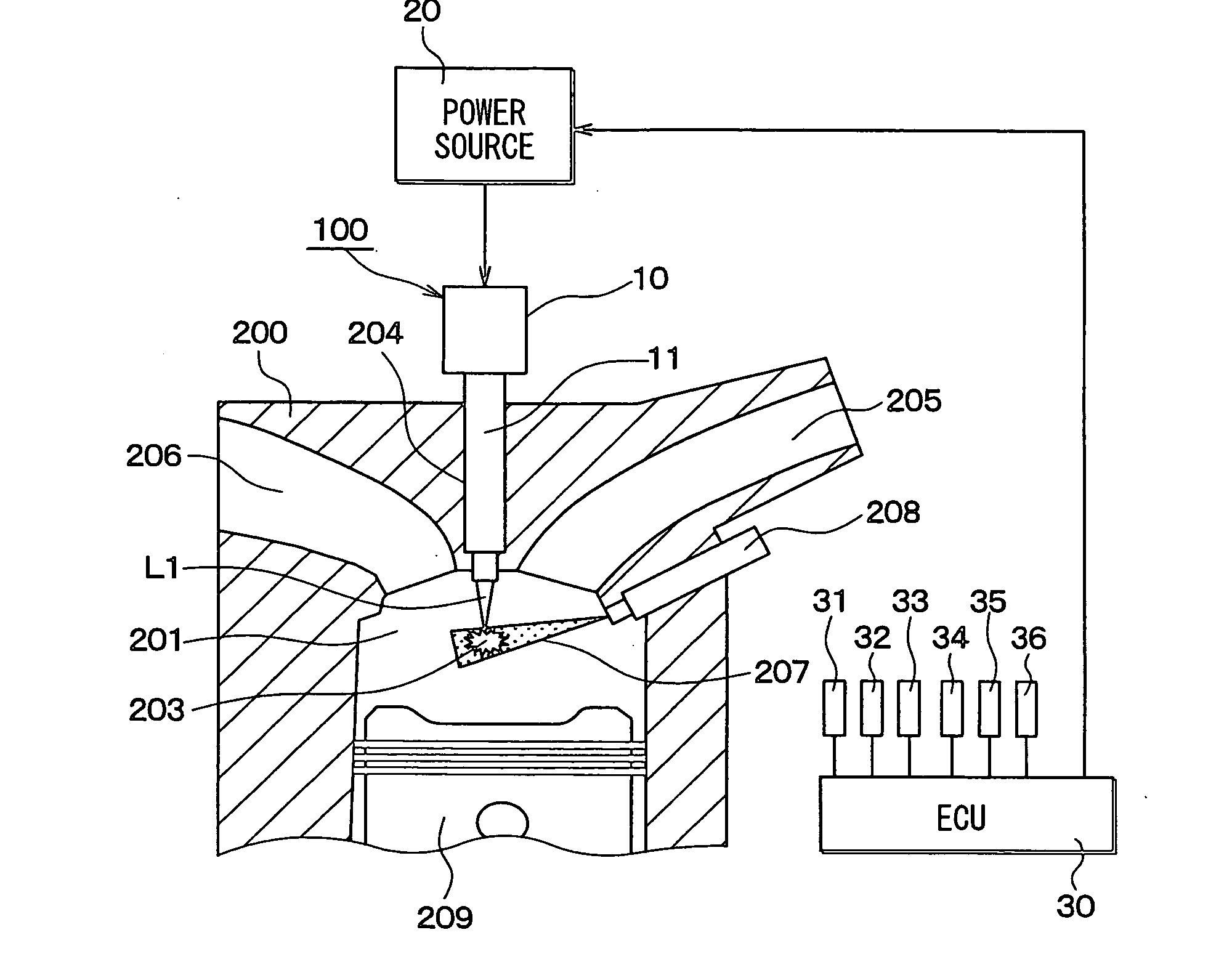
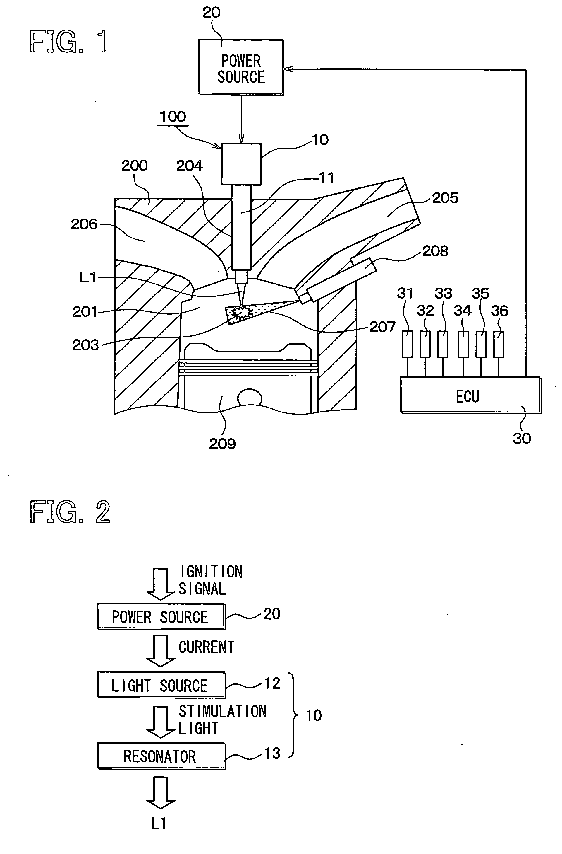
[0034] The laser type ignition device 100 is mounted on a portion of an engine cylinder head 200 near an engine combustion chamber 201, as shown in FIG. 1. Reference numerals 205, 206, 207, 208, 209 respectively indicate an intake manifold, an exhaust manifold, an air-fuel mixture, a fuel injector and a piston. The laser type ignition device 100 includes a laser oscillator 10 that provides a laser beam L1, an electric power source 20, an ECU 30 for controlling current supplied to the laser oscillator 10 and various sensors 31-36 for detecting engine conditions.

[0035] As shown in FIGS. 1, 2 and 10, the laser oscillator 10 includes a laser unit case 11, a laser diode (stimulation pumping source) 12 and a light resonator 13. The laser diode 12 and the light resonator 13 are held in the laser unit case 11. The laser oscillator 10 also includes various optical elements for co...

second embodiment

[0049] A laser type ignition device 110 according to the invention will be described with reference to FIGS. 7, 8 and 9.

[0050] Incidentally, the same reference numeral as the first embodiment represents the same or substantially the same portion, part or component as the first embodiment, hereafter.

[0051] The laser type ignition device 110 is equipped with an arrangement for detecting air-fuel mixture density. The arrangement is constituted of an observing window 40, a bandpass filter 41 and a photo detector 42. The observing window 40 is formed at a portion of the engine cylinder head 200 where the focal point 203 can be observed and closed by a transparent glass plate. The band pass filter 41 and the photo detector 42 are disposed in the window, as shown in FIG. 7. The above mixture density detecting arrangement can be integrated with the laser oscillator 10 and held in the case 11 thereof. In this case no such glass plate is necessary.

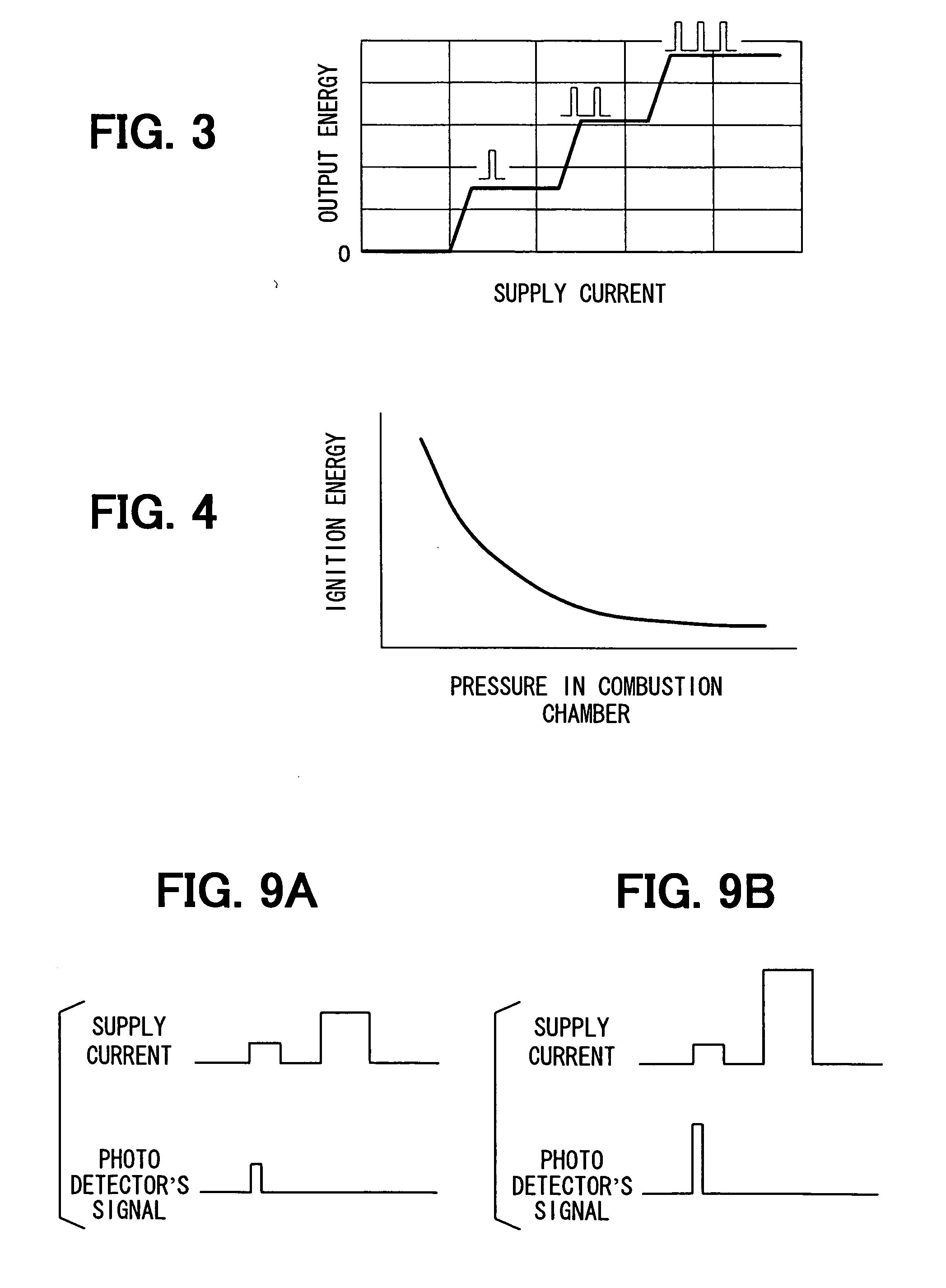
[0052] The laser oscillator 10 outputs, bef...


PUM


Abstract

A laser type ignition device for an internal combustion engine includes a laser oscillator mounted in the internal combustion engine so as to focus its laser beam on an air-fuel mixture supplied into the combustion chamber, a pressure sensor for detecting pressure in the combustion chamber, a power source for the laser oscillator and a control unit for controlling the power source to supply the laser oscillator with the current whose amount changes according to the pressure in the combustion chamber. The power of the laser beam increases as the pressure in the combustion chamber decreases to completely ignite the air-fuel mixture.

Description

CROSS REFERENCE TO RELATED APPLICATION [0001] The present application is based on and claims priority from Japanese Patent Application 2005-132191, filed Apr. 28, 2005, the contents of which are incorporated herein by reference. BACKGROUND OF THE INVENTION [0002] 1. Field of the Invention [0003] The present invention relates to a laser type engine ignition device for igniting an air-fuel mixture supplied into a combustion chamber of the engine by a laser. [0004] 2. Description of the Related Art [0005] Usually, the ignition condition of the combustion chamber changes very much according to engine operating condition, pressure, temperature, engine rotation speed, engine load, etc. Although it is necessary to properly control laser oscillation in order to secure complete ignition and a sufficient combustion speed, a conventional laser type ignition device, such as disclosed in JP-A-10-196471, can not sufficiently control laser oscillation, so that a complete ignition or a combustion s...

Claims


Application Information

Patent Timeline
IPC IPC(8): F02B19/00F02P23/00
CPCF02B23/104F02B2075/125F02D35/023F02D35/022Y02T10/125F02D41/1458F02P23/04Y02T10/12
Inventor ANEZAKI, YUKINOBUKANEHARA, KENJIABE, AKIYOSHINAGA, TOHRUTAIRA, TAKUNORI
Owner DENSO CORP
Why Eureka
Try Eureka